CDCP® Master Study Guide · R25-aligned · July 2026
Certification Mastery Edition
Certified Data Centre Professional (CDCP®)
R25-aligned master study guide — verified against current public EPI and EXIN information, 23 July 2026
Learn the system • Retrieve the details • Prove it under time
Prefer interactive study? Open the CDCP Guided Learning console →
Independent study aid for use alongside the mandatory authorized EPI R25 course material
LEARN THE SYSTEM • RETRIEVE THE DETAILS • PROVE IT UNDER TIME
Use Word's Navigation pane for subsection-level navigation. The entries below jump to every major section.
How to use this guide
This is an independent, R25-aligned mastery guide for the EXIN EPI Certified Data Centre Professional (CDCP®) examination. It is designed to help you learn the public syllabus deeply, connect the disciplines into one resilient system, and practise the reasoning demanded by a closed-book multiple-choice examination.
CDCP® and associated names and marks belong to their respective owners. This independent guide is not endorsed by, affiliated with, or a substitute for EPI, EXIN or an authorized training provider.
No honest guide can guarantee a perfect score. The exam bank is controlled by EPI/EXIN, current R25 module weights are not public, and a different set of questions can expose a different weakness. The purpose of the system below is to make 40/40 a credible target by demanding performance well above the pass line before you sit the exam.
Current official exam snapshot
| Item | Current official position (verified 23 July 2026) |
|---|---|
| Course release | EPI CDCP R25; the live English brochure is marked R25-01 |
| Level | Foundation; 2 ECTS credits |
| Course | Two days; instructor-led, virtual instructor-led, or Training On Demand |
| Prior experience | No formal prerequisite; one or two years in a data-centre or facilities environment is helpful |
| Training | Mandatory according to EXIN |
| Required reading | Course material provided by the trainer |
| Exam | 40 multiple-choice questions in 60 minutes; closed book |
| Pass threshold | 27/40. EXIN displays 68%, the rounded equivalent of 67.5% |
| Equipment | EXIN lists electronic equipment as not allowed |
| Certificate | Valid for three years; recertification is then required |
Official sources: EPI's live CDCP page and R25-01 brochure, and EXIN's CDCP certification page. Links appear in Sources and further reading.
What “ready for 100%” means
Do not use hours studied, pages highlighted, or familiarity as your readiness signal. Use observable performance. Book the exam only after you can meet all of these gates:
- Score at least 38/40 on two new, closed-book, timed 40-question mocks on different days. A 40/40 target needs headroom above the 27/40 pass line.
- Score at least 90% in every syllabus module, not merely overall. A strong power score must not conceal a weak fire-protection score.
- Give a one-sentence reason why the correct option is correct and why each distractor is inferior for every missed or guessed question.
- Complete routine single-phase, three-phase, availability, energy, lighting, and cooling conversions accurately without electronic aids when your course expects them.
- Draw the end-to-end power path, heat-removal path, TIA-942 cabling hierarchy, and monitoring/escalation loop from memory.
- Produce zero repeat errors on safety-critical distinctions after two correction cycles.
- Keep your predicted score within five percentage points of your actual score on the last three mixed quizzes. This is calibration: knowing what you do and do not know.
The R25 syllabus map
Public R25 course outlines present fourteen modules/topic areas. EPI and EXIN do not publish current R25 module weights. The “study share” below is a planning recommendation based on topic breadth, prerequisite structure, and how many later topics depend on the module; it is not a prediction of the exam distribution.
| Module | Public R25 scope, condensed | Suggested study share |
|---|---|---|
| 1. Mission-critical site | Business role, data-centre types and elements, causes of unavailability | 7% |
| 2. Standards | Standards, guidelines, subcomponent standards, international versus national requirements | 6% |
| 3. Location/building | Site and facility criteria, construction and supporting spaces | 7% |
| 4. Raised floor/ceiling | Types, loading, grounding, ramps, ceilings and cooling impact | 5% |
| 5. Lighting | Units, standards, fixture placement and emergency lighting | 3% |
| 6. Power | Generation-to-rack path, redundancy, UPS, batteries/BESS, distribution, quality, sizing, safety and sustainability | 20% |
| 7. EMF | Types, units, sources, effects and shielding | 4% |
| 8. Racks | Standards, dimensions, forms, security and rack power | 4% |
| 9. Cooling | Principles, environmental control, air management, containment, liquid cooling and STER | 15% |
| 10. Water | Uses, continuity, quality and backup supply | 3% |
| 11. Network infrastructure | Copper/fibre, TIA-942 topology, testing, redundancy and site connectivity | 9% |
| 12. Fire protection | Causes, detection, water/gas suppression, classes, extinguishers, signs and regulation | 8% |
| 13. Physical security/safety | Layered protection, access, surveillance and personnel safety | 4% |
| 14. Auxiliary systems | EMS, BMS, DCIM, leak detection, alarms, notifications and monitoring practice | 5% |
The four system stories
Facts become easier to recall when attached to a system story. Be able to tell these four stories without notes.
- Continuity story: a business service sets availability, capacity, recovery, security and compliance needs; those needs drive site, topology, redundancy, maintainability, procedures and monitoring.
- Power story: utility or on-site sources feed switchgear and transfer equipment; conditioned power passes through UPS and distribution to dual rack paths; stored energy bridges the generator start; protection, grounding, monitoring and maintenance make the chain safe.
- Heat story: almost all IT electrical energy becomes heat; cool air or liquid collects it at the equipment, transports it through a room or technology loop, transfers it to a facility loop, and rejects or reuses it outside the white space.
- Protection story: site choice and building construction avoid hazards; security deters, detects, delays and supports assessment and response; fire systems detect early and suppress safely; auxiliary systems turn physical conditions into timely, actionable alarms.
The learning system
The study method uses findings that are unusually consistent across learning research: retrieve information rather than only reread it; space successful retrievals over time; mix related problem types after initial instruction; compare your response with corrective feedback; and use worked examples before removing support. These methods often feel harder than rereading, but the feeling of fluency produced by rereading is a poor measure of durable learning.
Evidence behind the design
| Method | Current evidence used | Design consequence in this guide |
|---|---|---|
| Retrieval practice | A 2021 classroom meta-analysis synthesized 222 studies and 48,478 learners and found a medium benefit (g ≈ 0.50); transfer beyond repeated facts is positive but smaller and depends on practice design | Every module ends with closed-book prompts; correct guesses still enter the error log; practice includes scenarios and calculations |
| Spaced retrieval | A 2021 meta-analysis found spaced retrieval superior to massed retrieval (g ≈ 0.74); a 2025 applied-classroom synthesis also reported a meaningful advantage | Successful recalls return after increasing delays; the stated 1-3-7-14-28-day sequence is a practical heuristic, not a universal optimum |
| Explanatory feedback | A large 2020 synthesis found an average benefit (d ≈ 0.48) with high variation; information-rich feedback outperformed bare reward/punishment | Answer keys explain the governing principle and distractor, followed by delayed retesting |
| Worked examples and fading | A 2023 mathematics meta-analysis found a moderate benefit (g ≈ 0.48); 2025 evidence on expertise reversal supports more assistance for novices and less for experts | New calculations begin with a worked solution, then a partial completion, then an unsupported and finally mixed problem |
| Interleaving | A meta-analysis found an overall advantage (g ≈ 0.42), but effects varied by material and did not favour mixing every kind of text or word learning | Initial instruction stays coherent; only related, confusable concepts are mixed after basic competence |
| Self-explanation and calibration | Self-explanation has an average positive effect, but unchecked explanations can rehearse errors; delayed judgments improve monitoring more than memory itself | Explanations are checked against authoritative feedback, confidence is recorded before feedback, and high-confidence errors receive priority |
| Sleep | A 2024 meta-analysis found restricted sleep impaired memory formation (g ≈ 0.29); the adult sleep consensus recommends at least seven hours regularly for healthy adults | The plan protects sleep throughout preparation and replaces the last-night cram with a short retrieval pass |
Effect sizes summarize averages across varied learners and tasks. They cannot be converted into CDCP score points, and none establishes a probability of 40/40. Exact spacing intervals, session length, mock count and readiness thresholds below are practical decisions built on the evidence, not experimentally proven universal constants.
The RETAIN loop
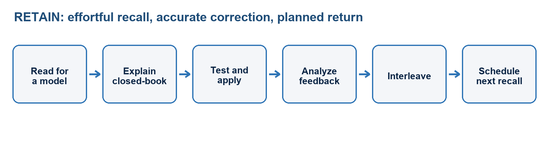
Use the same six-step loop for every concept.
- Read for a model. Read a short section of the authorized material and this guide. Ask: What problem does this component solve? Where does it sit in the system? What can make it fail?
- Explain without notes. Close the source and teach the idea aloud or on paper in plain language. Include one contrast, such as ATS versus STS or BMS versus DCIM.
- Test. Answer short-response prompts before looking at options. Then answer mixed multiple-choice questions and do any relevant calculation.
- Analyze feedback. Check the full explanation, not only the letter. Diagnose the error as knowledge, distinction, calculation, reading, or confidence.
- Interleave. Mix the new topic with two confusable or dependent topics. Examples: grounding/bonding/earthing; bypass/recirculation; wet/pre-action/gaseous suppression; EMS/BMS/DCIM.
- Next review. Schedule the item for another closed-book retrieval at roughly 1, 3, 7, 14 and 28 days, adapting the interval to your result.
“RETAIN” is a memory label for this guide, not an official EPI method.
A high-yield 75-minute session
- Minutes 0–7 — cumulative brain dump: write everything you remember about one earlier module, then mark gaps in a different colour.
- Minutes 7–25 — model building: study one small new section and one worked example. Convert it into a diagram, comparison, or causal chain.
- Minutes 25–43 — closed-book retrieval: answer prompts or blank-page questions. Do not peek. Retrieval that is effortful but ultimately correct is the goal.
- Minutes 43–63 — mixed application: solve 8–12 questions drawn from the new topic and at least two earlier topics. Explain the discriminating clue.
- Minutes 63–72 — corrective feedback: update the error log and write a corrected rule in your own words.
- Minutes 72–75 — schedule: set the next review and choose the first question for the next session.
For a 35-minute session, use 4, 7, 8, 8, 5 and 3 minutes for brain dump, model building, retrieval, mixed practice, corrective feedback and scheduling. Protect the retrieval and feedback phases; shorten the reading phase first.
Spacing rules that are simple enough to follow
Use a default review sequence of same day, +1 day, +3 days, +7 days, +14 days and +28 days. A review is a closed-book attempt, not exposure.
- If recall is complete and the explanation is precise, move to the next interval.
- If recall is partial, study the correction, retrieve it again after a short delay, and repeat the current interval.
- If recall is absent or confidently wrong, return to a worked example and shorten the next interval.
- Do not create hundreds of cards before using them. A smaller deck of decisions, contrasts, causal chains and formulas is more valuable than a deck of copied sentences.
- Use both free recall and recognition. The real exam is multiple-choice, but short-answer retrieval exposes gaps that answer options can hide.
Interleave after you can perform the basics
Initial blocked practice is useful for a novice learning a procedure. Once you can solve a basic example, mix related categories so that you must first decide which principle applies.
High-value CDCP mixes include:
- N+1, N+2, 2N and 2(N+1)
- ATS, STS, UPS bypass and maintenance bypass
- kW, kVA, power factor, kWh and heat load
- sag, swell, transient, interruption, harmonic distortion and imbalance
- bypass air, recirculated air, negative pressure and short-circuit airflow
- CRAC, CRAH, in-row, rear-door, direct-to-chip and immersion cooling
- bonding, grounding/earthing, shielding and signal reference concepts
- ER, MDA, HDA, ZDA and EDA
- wet pipe, dry pipe, pre-action and gaseous total flooding
- EMS, BMS and DCIM
- tailgating, piggybacking, anti-passback and mantrap/interlock controls
Worked example → completion → independent problem
For calculations and system sequences, use fading:
- Study a fully worked example and explain every step.
- Complete an example with the formula and first step supplied.
- Solve a new problem without support.
- Solve a mixed problem in which you must choose the formula or topology.
- Explain why a plausible wrong method fails.
Do not begin with a long set of unsupported calculations if you cannot yet identify the variables and units. Do not remain with worked examples after you can solve them; remove support so retrieval and transfer occur.
Corrective feedback and the error log
Use one row per defect, not one row per question attempt.
| Field | What to record |
|---|---|
| Date/source | When and where the error occurred |
| Module | One of the fourteen R25 modules |
| Prompt | A short paraphrase, never copied protected exam content |
| My rule | The rule you applied, including the wrong assumption |
| Correct rule | A precise, affirmative correction in your own words |
| Error type | Knowledge, distinction, calculation, reading, or confidence |
| Discriminator | The word, unit, topology clue, or safety principle that decides the item |
| Retest dates | +1, +3, +7 and later dates until two clean recalls |
Five error types and their fixes
- Knowledge gap: you did not know the fact. Fix with a short explanation, a retrieval card and two spaced recalls.
- Distinction error: you knew both terms but confused them. Fix with a two-column contrast and a scenario that forces the choice.
- Calculation error: you selected the correct concept but mishandled units or arithmetic. Fix with a worked example, unit check and two new values.
- Reading error: you missed “except,” “first,” “most,” or another qualifier. Fix by circling the task word and restating the question before choosing.
- Confidence error: you were confidently wrong or changed a correct answer without evidence. Fix by recording the misleading cue and demanding a reason before changing an answer.
Sleep, recovery and attention
Learning continues after the study session. Current reviews support a role for sleep in memory formation, and sleep restriction impairs encoding and consolidation. Most healthy adults should plan for at least seven hours of sleep regularly, with individual needs and medical advice taking priority.
- End the final heavy study session early enough to preserve normal sleep.
- Prefer a short retrieval review the evening before and the morning of the exam to an all-night cram.
- Use breaks when attention falls. Distributed high-quality sessions beat one exhausted block.
- Reproduce exam conditions during mocks: one sitting, no notes, no phone, fixed time and no interruptions.
Six-week mastery plan
This is a 45–60 hour plan for a learner with some IT or facilities background. Add 25–50% more time if the electrical, mechanical and cabling material is new. Use the authorized R25 course on the dates assigned by your provider and move the relevant retrieval sessions to immediately after class.
| Week | Primary learning | Cumulative retrieval and output | Gate to advance |
|---|---|---|---|
| 0: Baseline | Exam rules; diagnostic; glossary setup | Draw all four system stories from current knowledge | Baseline recorded; weak modules ranked |
| 1: Context | Modules 1–5: mission, standards, site, floors/ceilings, light | Site-selection risk review; standards hierarchy; floor-load and lux drills | 80% on a 25-item mixed quiz; explain every miss |
| 2: Power | Module 6 end to end | Draw power path; compare redundancy; daily kW/kVA/three-phase drills | 85% power quiz plus 100% on safety-critical distinctions |
| 3: Heat and hardware | Modules 7–10: EMF, racks, cooling, water | Heat-path drawing; containment diagnosis; rack A/B design; water-risk review | 85% on Modules 7–10 and no unit confusion |
| 4: Connectivity and protection | Modules 11–14: network, fire, security/safety, auxiliary systems | Draw cabling hierarchy; fire scenario decisions; alarm escalation design | 85% on Modules 11–14; explain jurisdiction-dependent choices |
| 5: Integration | Mixed scenarios across all modules | 20–30 mixed items per day; formula sheet from memory; Mock 1 | At least 36/40; remediate every K/U/G defect |
| 6: Exam readiness | Weak-module repair and two novel simulations | Mock 2 and final simulation on different days; light spaced review | Two scores ≥38/40; every module ≥90%; calibration gap ≤5 points |
Fourteen-day accelerator
Use only if the exam date cannot move. Plan 3–4 focused hours per day split into two or three sessions; do not convert it into one nightly cram.
- Days 1–2: diagnostic; mission, standards, site, floors and lighting.
- Days 3–5: power, including one calculation set each day.
- Days 6–7: racks, cooling, water and EMF.
- Days 8–9: network infrastructure.
- Day 10: fire protection.
- Day 11: security, safety and auxiliary systems.
- Day 12: full cumulative retrieval and Mock 1.
- Day 13: error-driven repair in the morning, then a second fresh timed simulation later only after every Mock 1 defect has been corrected.
- Day 14: one light closed-book retrieval pass, formulas/acronyms and logistics; stop early and preserve normal sleep. If the readiness gates are not met, postpone when the booking rules permit.
If Mock 1 is below 34/40 or any module is below 80%, postpone the exam if the booking rules permit. A short deadline does not change the knowledge threshold.
Baseline diagnostic
Answer these without notes before your first full study session. Use one sentence, a sketch or a calculation. Score one point only when the answer is both correct and explained. The answer key follows the questions; do not look ahead.
Q01 — Distinguish availability, reliability and maintainability.
Q02 — Name four data-centre types and one business implication of each.
Q03 — Put law/regulation, an adopted code, a voluntary standard, a guideline and a site procedure into a sensible authority hierarchy.
Q04 — List six independent site-selection hazards or constraints.
Q05 — Distinguish uniform, concentrated and rolling floor loads.
Q06 — Define lumen and lux, and calculate the average illuminance from 10,000 lumens uniformly reaching 200 square metres.
Q07 — Explain N, N+1, 2N and 2(N+1) without using the word “backup” alone.
Q08 — Compare an ATS and an STS by source type, switching mechanism and typical use.
Q09 — A 400 V three-phase load draws 100 A at power factor 0.9. Ignoring efficiency losses, estimate real power.
Q10 — Distinguish real power, apparent power and energy.
Q11 — Name five power-quality disturbances and one mitigation for each.
Q12 — Why can a single-corded server defeat an otherwise dual-path rack design, and what component can address the issue?
Q13 — Distinguish an electric field from a magnetic field and give one mitigation shared by both.
Q14 — What does one rack unit (1U) measure, and why do rack depth and dynamic load matter?
Q15 — Explain bypass air and recirculation in a data hall.
Q16 — Compare a CRAC with a CRAH.
Q17 — Convert 100 kW of IT power to approximate heat output in Btu/h.
Q18 — Name three forms of liquid cooling and the role of a CDU.
Q19 — Give three reasons a data centre may require backup water, and three measures that limit water damage.
Q20 — Expand and order ER, MDA, HDA, ZDA and EDA in the TIA-942 cabling hierarchy.
Q21 — Distinguish copper certification tests from fibre certification tests at a high level.
Q22 — Why are two carrier contracts not necessarily two diverse site connections?
Q23 — Compare wet-pipe, dry-pipe and pre-action sprinkler systems.
Q24 — Why must a gaseous total-flooding system be paired with room integrity, warning, egress and shutdown logic?
Q25 — State five useful functions of layered physical security.
Q26 — Distinguish tailgating, piggybacking and anti-passback.
Q27 — Distinguish EMS, BMS and DCIM by primary scope.
Q28 — Design a basic alarm path from sensor to accountable human response, including what prevents alarm fatigue.
Diagnostic answer key
Q01 — Availability is the proportion of required time a service is usable; reliability is the probability of failure-free operation for a stated time/condition; maintainability is the ease and speed of restoring or servicing it. Availability is influenced by both failure frequency and restoration time.
Q02 — Examples: enterprise (serves one organisation and its risk priorities), colocation (shared facility with provider/customer responsibility boundaries), hyperscale/cloud (very large, standardized and automation-heavy), edge (small and close to users for latency but often lightly staffed), modular (prefabricated/scalable), and HPC/AI (very high density and cooling/power intensity).
Q03 — Applicable law/regulation and AHJ direction prevail; an adopted code is enforceable through that authority; a contractually adopted standard then sets agreed requirements; guidelines recommend practice; site procedures implement the controlling requirements. Exact relationships vary by jurisdiction and contract.
Q04 — Any six well-explained items such as flood level, seismic risk, severe weather, wildfire, adjacent hazardous industry, aircraft/rail/road exposure, crime/civil disturbance, utility capacity/quality, carrier diversity, water availability, fuel delivery, pollution, access, workforce, permits, latency and expansion land.
Q05 — Uniform load is distributed over an area; concentrated load is applied over a small footprint/point; rolling load is the moving load imposed while equipment is transported and can exceed its static effect at panel edges or transitions.
Q06 — Lumen measures luminous flux; lux is lumens per square metre at a surface. 10,000/200 = 50 lux, assuming uniform delivery and ignoring losses.
Q07 — N is exactly the capacity/components required for design load; N+1 adds one unit of the chosen module size; 2N provides two complete capacity systems/paths; 2(N+1) provides two complete paths, each with its own extra unit. The notation alone does not prove independence.
Q08 — An ATS is an electromechanical transfer device commonly moving a load between utility/generator or other AC sources, with a finite transfer; an STS uses solid-state switching between compatible live AC sources for very fast transfer to critical loads. Each source must remain within the STS's permitted voltage, frequency and phase-angle transfer window; perfect synchronism is not a universal criterion.
Q09 — P ≈ √3 × 400 V × 100 A × 0.9 ≈ 62.4 kW.
Q10 — Real power (kW) performs work and becomes heat; apparent power (kVA) is the RMS voltage-current product used to size AC equipment; energy (kWh) is power integrated over time.
Q11 — Examples: sag—ride-through/UPS; swell—voltage regulation; interruption—UPS/generator; transient—surge protective device; harmonics—filters/appropriate transformer and conductor design; frequency deviation—UPS/generator control; imbalance—phase-load correction. The best mitigation depends on the measured source.
Q12 — A single-corded device can accept only one rack source, creating a single point even when A and B feeds exist. A suitable rack/static transfer switch can select between compatible sources, subject to design and load requirements.
Q13 — Electric fields arise from voltage and are measured in V/m; magnetic fields arise from current and are commonly expressed as tesla/gauss or A/m. Increasing separation reduces exposure to both; shielding materials and geometry differ by field and frequency.
Q14 — 1U is 1.75 inches or 44.45 mm. Depth must accommodate the device, bend radius, cables and service clearance; dynamic/rolling loads govern safe movement and can be more severe than the final static load.
Q15 — Bypass air reaches the return without cooling IT; recirculated hot air re-enters IT inlets. Both waste cooling capacity and raise thermal risk, but they are different flow failures.
Q16 — A CRAC normally uses a direct-expansion refrigerant circuit at the room unit; a CRAH uses a chilled-water coil supplied by central plant. Product designs vary, so identify the heat-transfer medium rather than relying only on the label.
Q17 — 100 kW × 3,412 Btu/h per kW ≈ 341,200 Btu/h.
Q18 — Direct-to-chip cold plates, rear-door heat exchangers and immersion are examples. A coolant distribution unit pumps/controls a technology loop and transfers heat to a facility loop while providing separation, monitoring and coolant/fluid-quality control as designed.
Q19 — Cooling towers, chilled-water systems, humidification, fire protection and domestic/safety services can require water continuity. Limit damage with route separation, secondary containment/drip trays, zoned isolation valves, leak detection, drains and maintained response procedures.
Q20 — Entrance Room → Main Distribution Area → Horizontal Distribution Area → optional Zone Distribution Area → Equipment Distribution Area. Actual designs may omit optional stages or use permitted variants.
Q21 — Copper certification commonly checks wire map, length, insertion loss, return loss and crosstalk metrics; fibre checks polarity/continuity, length and optical loss, with OTDR used where appropriate for event/location analysis. Test to the specified standard and link class.
Q22 — Both carriers may share the same duct, manhole, bridge, entrance room or upstream route. True diversity requires verified physical and logical separation with common-mode dependencies identified.
Q23 — Wet-pipe piping contains water; dry-pipe piping contains pressurized air/nitrogen until sprinkler operation opens the dry valve; pre-action piping is normally dry and uses a separately defined release sequence. Single-interlock, non-interlock and double-interlock pre-action arrangements do not use identical valve logic, so the approved design, listing and local code govern admission and discharge.
Q24 — The enclosure must retain the design concentration long enough to work; alarms and time delay protect occupants; safe egress and agent-specific hazards must be addressed; ventilation/power shutdown and dampers prevent agent loss or re-ignition as designed. Approval and testing by the AHJ are essential.
Q25 — Deter, detect, delay, assess and respond. Some frameworks condense this to four functions by treating assessment as part of response; learn the authorized course convention.
Q26 — Tailgating is unauthorized following without the authorized person's informed cooperation; piggybacking commonly implies knowing assistance; anti-passback prevents a credential from being reused inconsistently with its recorded entry/exit state. Usage can vary, so learn the course wording.
Q27 — EMS focuses on environmental sensing/alarms; BMS monitors and controls building mechanical/electrical systems; DCIM integrates facility, capacity, energy, asset and often IT-context information for data-centre management. Products overlap, but the primary scope differs.
Q28 — Sensor → local controller/gateway → resilient monitoring platform → threshold and persistence logic → severity classification → notification to an owned on-call role → acknowledgement → runbook action/escalation → closure and review. Priorities, deadbands/delays, dependency suppression, maintained contacts and periodic testing reduce nuisance alarms and alarm fatigue.
Interpreting the baseline
- 24–28: strong starting model; focus on precision, current R25 additions and eliminating guesses.
- 18–23: workable foundation; follow the full plan and concentrate on weak clusters.
- 10–17: significant gaps; add worked examples, site walk-throughs or instructor questions before heavy mock testing.
- 0–9: begin with system stories and vocabulary; allow more than six weeks if possible.
The baseline is intentionally harder than a recognition quiz. It is a learning map, not a predicted exam score.
Coverage. This draft follows the publicly listed EPI CDCP R25 syllabus for: (1) The Mission Critical Site; (2) Data Centre Standards; (3) Data Centre Location, Building and Construction; (4) Raised Access Flooring and Suspended Ceiling; (5) Light; (6) Power Infrastructure; and (7) Electromagnetic Fields. It is an original learning aid, not an EPI course replacement, an official exam blueprint, or a collection of recalled exam questions. No current R25 module weighting is inferred. Standards and code editions were checked on 23 July 2026; always confirm the edition adopted by the authority having jurisdiction (AHJ) and the project contract.
Module 1 — The Mission Critical Site
What mastery looks like
You can start with a business service, identify the IT and facility dependencies that keep it available, and explain how a failure in any dependency can interrupt the service. You can distinguish common data-centre business models; use availability, reliability, resilience, maintainability, RTO and RPO correctly; recognize common-mode and human-caused failure; and convert a business impact into proportionate design and operating controls. You do not equate “more equipment” with resilience or a marketing label with an end-to-end service outcome.
Core concepts
Mission critical is an impact statement. A site or system is mission critical when loss or serious degradation would cause unacceptable harm—such as loss of safety, revenue, legal compliance, public service, reputation or strategic capability. “Unacceptable” is defined by the organization through business-impact analysis and risk appetite; it is not inherent in a server room’s size.
The business-to-infrastructure chain. Reason from the outside inward:
- Business mission and products depend on business processes.
- Processes depend on applications, data and communications.
- Those depend on compute, storage and network equipment.
- IT equipment depends on space, power, cooling, cabling, fire protection, physical security, monitoring and trained operations.
- All layers depend on external utilities, suppliers, people, access and governance.
An availability claim is meaningful only when its boundary is stated. A resilient electrical plant does not make a service available if a single carrier, database, authentication service or operator action can stop it.
Business organization and ownership. Useful roles include executive sponsor, business/service owner, IT, facilities engineering, network, security, safety, risk/compliance, finance/procurement, operations and vendors. Clarify who is accountable for the outcome, who operates each asset, who may authorize change, who responds to alarms, and who owns each interface. Many incidents arise at organizational handoffs rather than inside a component.
Types of data centre. Classifications overlap; do not treat them as a single ladder.
- Enterprise/private: supports one organization, usually with direct control over risk, hardware and operations.
- Colocation/multi-tenant: sells secured space, power, cooling and connectivity; the provider/customer responsibility boundary and SLA are central.
- Managed hosting: provider operates some or all customer IT in addition to facility services.
- Cloud/hyperscale: large, highly standardized infrastructure providing elastic services; application-level resilience may span rooms, sites or regions.
- Edge: smaller facility close to users, devices or data sources to reduce latency or bandwidth; remote/unmanned operation and limited local support become important.
- Modular/containerized: a construction/deployment form, not a business model or an automatic availability level.
- Disaster-recovery/secondary site: supports continuity after disruption; success depends on replication, capacity, procedures and testing, not merely owning another room.
Also distinguish an owned site, a leased/colocation site, and outsourced service. Control, visibility, audit rights and responsibility change even when the physical technology looks similar.
Elements of a data centre. A useful system model has six interacting groups:
- IT and telecom: compute, storage, network, carrier entrance, meet-me and distribution.
- Electrical: utility or alternate sources, switchgear, generators, transfer devices, UPS/energy storage, distribution and protective bonding.
- Mechanical/environmental: heat rejection, cooling, airflow or liquid loops, water management and environmental monitoring.
- Building/life safety/security: structure, envelope, compartments, detection, suppression, egress, access control and surveillance.
- Monitoring/control: BMS/BAS, electrical power monitoring system (EPMS), environmental monitoring system (EMS), DCIM, alarms, sensors and communications.
- People/process: staffing, procedures, maintenance, spares, change control, incident response, training, documentation and supplier support.
Availability-related terms. Availability is the probability or proportion of time that a service is usable when required. Reliability is the probability it performs without failure over a stated time and conditions. Maintainability is the ability to restore or maintain it efficiently. Resilience is the ability to withstand, adapt to and recover from disruption. Redundancy is duplication or excess capacity; it is one technique, not the result itself. Fault tolerance means the required function continues after defined fault(s). Concurrent maintainability means planned maintenance can occur without interrupting the critical load. These properties must be demonstrated at system level.
Continuity objectives. The recovery time objective (RTO) is the target maximum time to restore a service after disruption. The recovery point objective (RPO) is the target maximum tolerable data-loss interval, expressed as time before the disruption. Neither is a guarantee. A generator helps facility continuity but does not by itself satisfy an application RPO.
Causes of unavailability. Think in categories, then look for interactions:
- utility loss or poor power quality; failed transfer, switchgear, UPS, battery or generator;
- cooling or heat-rejection failure, airflow blockage, leak or control instability;
- carrier/path loss, cabling damage or network misconfiguration;
- fire, smoke, water, severe weather, earthquake, contamination or construction work;
- cyberattack or failure of a shared control/monitoring platform;
- capacity exhaustion, configuration error, software defect or unsuccessful change;
- poor maintenance, latent defect, missing spares, expired fuel/support or documentation error;
- deliberate action, unauthorized access, theft or sabotage;
- upstream supplier, logistics, workforce or fuel disruption.
Human contribution is often systemic: ambiguous procedure, poor interface design, fatigue, inadequate training or change pressure. “Operator error” should trigger causal analysis, not end it.
Key distinctions
| Pair | Correct distinction |
|---|---|
| Availability vs reliability | A repairable system can have high availability despite more frequent failures if restoration is fast; reliability focuses on failure-free operation. |
| Resilience vs redundancy | Resilience is an outcome across prevention, response and recovery; redundancy is only one design measure and may share a common failure. |
| Site availability vs service availability | Site infrastructure is one dependency. Application architecture, networks, data and other sites also determine the user-visible service. |
| Incident vs disaster | An incident is any disruption requiring response; a disaster exceeds ordinary response capability and activates continuity/recovery arrangements. Local policy defines thresholds. |
| RTO vs RPO | RTO is targeted restoration time; RPO is targeted data-loss window. |
| SLA vs architecture | An SLA states measurable commitments and remedies; architecture is how the service may meet them. A label alone proves neither. |
| Capacity redundancy vs path redundancy | Spare units protect loss of capacity; independent distribution paths protect path failure. One does not imply the other. |
| Hazard vs risk | A hazard is a potential source of harm; risk combines likelihood, consequence and uncertainty under stated conditions. |
Formulas and units
Observed availability over a stated period:
A=(required time-unavailable time)/(required time)
State whether planned maintenance, degraded service and excluded periods count. “Five nines” without a measurement window and definition is incomplete.
For an idealized repairable component with approximately constant failure and repair rates:
A≈ (MTBF)/(MTBF+MTTR)
MTBF is mean time between failures; MTTR must be defined (repair, restore or recover). This approximation is not a substitute for dependency modelling and does not capture maintenance errors, common-cause failures or non-constant aging.
If service is required continuously for a 365-day year, the approximate downtime allowances are: 99.9% = 8 h 45 min 36 s; 99.99% = 52 min 34 s; 99.999% = 5 min 15 s. These are arithmetic illustrations, not guaranteed design outcomes or automatic Tier/Rating mappings.
For simple independent series dependencies, A(system) = A₁ × A₂ × … × Aₙ; every required series element reduces total availability. For ideal independent parallel alternatives, A(parallel) = 1 − (1 − A₁)(1 − A₂). Real redundant paths are rarely independent, so explicitly model shared switchgear, controls, fuel, rooms, staff and procedures.
Design and operations reasoning
Use this reasoning sequence for a scenario:
- Define scope and required function. What user outcome, load and time period matter?
- Establish impact and targets. What are the consequence, RTO, RPO, capacity, compliance and security needs?
- Map dependencies and failure domains. Follow power, cooling, communications, controls, people and supplies from source to load.
- Identify single points and common modes. Two components in one room, under one controller, on one fuel supply or changed by one procedure may not be independent.
- Choose proportionate controls. Avoid, reduce, transfer or accept risk; combine topology with detection, procedures, spares and recovery.
- Validate. Review design, commission under load and failure conditions, train, exercise emergency procedures, trend alarms and revalidate after change.
Example: two UPS modules do not establish continuity. Ask whether the load needs both, whether maintenance isolates safely, whether bypass is shared, whether downstream distribution is dual, whether dual-corded equipment uses separate paths, and what happens during a fault while one unit is unavailable. This end-to-end challenge is more valuable than counting boxes.
Common traps
- Treating “mission critical” as synonymous with large, expensive or 24×7.
- Quoting availability percentages without the service boundary, measurement period and exclusions.
- Assuming two items are independent because their labels are A and B.
- Focusing on equipment failure while ignoring maintenance, controls, configuration and people.
- Equating a component’s MTBF with system uptime.
- Believing an SLA prevents downtime; it allocates commitments and consequences.
- Designing only for normal peak load and not for maintenance or post-fault conditions.
- Assuming a second site is recovery-ready without replicated data, sufficient capacity, dependencies and rehearsed procedures.
Closed-book retrieval prompts
- Q: What makes a site “mission critical”? A: Loss or degradation would create impact beyond the organization’s defined tolerance; the designation comes from business impact and risk appetite.
- Q: Name the six broad data-centre element groups. A: IT/telecom; electrical; mechanical/environmental; building/life-safety/security; monitoring/control; people/process.
- Q: Reliability versus availability? A: Reliability is failure-free performance over time; availability is readiness for use and includes restoration.
- Q: RTO versus RPO? A: RTO targets time to restore; RPO targets the tolerable data-loss interval.
- Q: Why can duplicated equipment still be a single failure domain? A: It may share a source, path, room, control, procedure, fuel or other common dependency.
- Q: What is the first question when someone claims “99.999% available”? A: Available for which service, over what required period, measured how, with what exclusions?
- Q: Why is a second data centre not automatically a disaster-recovery solution? A: Applications, data, capacity, network dependencies, people and failover/failback procedures must also work and be tested.
- Q: Give a sound response to “human error caused the outage.” A: Examine conditions that enabled it—procedure, training, interface, authorization, fatigue, supervision and change design—and correct the system.
Module 2 — Data Centre Standards
What mastery looks like
You can explain why standards are used, distinguish a standard from a law, code, guideline and certification, select documents by scope, and resolve requirements through the AHJ and contract. You recognize the principal data-centre facility families and important subsystem standards, but you do not blend their classification schemes or assume that a certificate under one scheme proves compliance with another.
Core concepts
Why use standards. Standards create common terminology, minimum requirements or recommended practices; make designs auditable; improve interoperability and safety; support procurement and acceptance; and preserve institutional knowledge. They do not replace a site-specific risk analysis, competent engineering or commissioning.
Document hierarchy. Exact legal hierarchy varies, but use this mental model:
- Law/regulation: issued by government and legally binding in its jurisdiction.
- Code: a consolidated set of rules; enforceable when adopted by legislation, regulation, permit condition or contract.
- Standard: consensus or technical specification from a recognized body; normally voluntary until adopted or incorporated by reference.
- Guideline/recommended practice: advisory methods; may become contractually binding when specified.
- Manufacturer instruction/listing condition: product-specific safe-use requirement, often enforceable through adopted code.
- Owner’s design requirement/contract specification: project obligation; it can be more stringent than code but cannot lawfully waive mandatory requirements.
- Conformity attestation: a statement that a defined object met specified requirements at a point in time. In ISO/IEC conformity-assessment terminology, certification is third-party attestation; a first-party claim is a supplier's declaration of conformity. The attestation is not the underlying standard and does not eliminate operating risk.
Normative language matters: shall generally denotes a requirement; should a recommendation; may permission; can possibility. Confirm each document’s definitions. Annexes may be normative or informative.
Primary facility-wide families. Know scope rather than memorizing page-level requirements:
- ANSI/TIA-942-C (2024), Telecommunications Infrastructure Standard for Data Centers: architecture, telecom, power, cooling, fire protection, security, safety and monitoring for data-centre types from edge to hyperscale. TIA publishes Rated-1 through Rated-4 certification levels.
- ISO/IEC 22237 series: international data-centre facilities and infrastructure family. Part 1 covers general concepts and classification around availability, security and energy-efficiency enablement; Part 2:2024 building construction; Part 3:2021 power distribution; Part 4 environmental control; Part 5 telecom cabling (a new edition was still in formal development as of the reference date); Part 6:2024 security; Part 7 operations/management (2018 technical specification, with a replacement draft in development). Use only published/adopted editions for a compliance claim.
- EN 50600 series: European data-centre facilities and infrastructure family and an important basis for ISO/IEC 22237. A European standard may be nationally adopted with a national prefix; national annexes and law still matter.
- ANSI/BICSI 002-2024: broad data-centre design standard/best-practice resource. ANSI/BICSI 009-2024 addresses operations.
- Uptime Institute Tier Standard: Topology: outcome-based topology classification: Tier I Basic Capacity, Tier II Redundant Capacity Components, Tier III Concurrently Maintainable, Tier IV Fault Tolerant. It is proprietary and distinct from TIA Rated levels and ISO/EN classifications.
These schemes have different owners, terminology, scope, evidence and certification processes. Similar words do not establish equivalence. Never relabel a facility “Tier III” merely because it has N+1 UPS units or meets another scheme’s level 3.
Subsystem map. A data-centre project normally needs multiple coordinated references:
- electrical installation and safety: the locally adopted electrical code (for example NFPA 70/NEC in relevant U.S. jurisdictions or the national implementation of IEC 60364), plus product standards;
- fire/life safety: local building/fire code, NFPA or national equivalents, and fire authority requirements;
- lightning and surge protection: locally adopted IEC 62305/NFPA 780 or equivalents;
- UPS: IEC 62040 series; static transfer systems: IEC 62310 series;
- enclosure ingress protection: IEC 60529 IP Code; North American enclosure “Type” ratings are a different system and are not numerically interchangeable with IP;
- bonding/earthing and telecom: ISO/IEC, TIA, BICSI and the electrical code, coordinated as a single safety system;
- cabling: ISO/IEC 11801 series, CENELEC EN 50173 series, ANSI/TIA-568 family and TIA-942 as applicable;
- environmental conditions: ASHRAE’s Thermal Guidelines/Data Center Resources, manufacturer limits and the chosen facility standard;
- lighting: ISO/CIE 8995-1:2025 and applicable national workplace/emergency-lighting rules;
- raised floors: applicable structural/access-floor product standards such as EN 12825 or national equivalents, plus facility and seismic requirements;
- EMC/human exposure: IEC 61000 family and product EMC standards; ICNIRP/IEEE/national exposure rules; do not confuse equipment compatibility with human exposure;
- security and management: ISO/IEC 27001 where an information-security management system is in scope, ISO/IEC 22237-6 for facility security systems, and local privacy/security law;
- energy: ISO/IEC 30134 KPI family; ISO/IEC 30134-2:2026 defines PUE.
International versus national. ISO and IEC publish international standards; CEN/CENELEC publish European standards; national bodies adopt, modify or supplement them. ANSI accredits U.S. standards development but “ANSI” does not make a document law. NFPA publishes codes/standards widely adopted in the U.S. and elsewhere, but the adopted edition and local amendments control. A global design basis therefore needs a code-and-standards register for the actual country, city, utility, insurer and customer.
Conformity and evidence. Separate four questions:
- What is the claimed object—design documents, constructed facility, product, process or management system?
- What exact standard, edition, clauses and classification are in scope?
- Who assessed it, using what competence/independence and evidence?
- How long is the attestation valid, and how are changes/surveillance handled?
A listed product is not a certified facility. A design certificate does not prove construction matches the design. A constructed-facility assessment does not guarantee future operation after unreviewed changes.
Key distinctions
| Pair | Correct distinction |
|---|---|
| Standard vs code | A standard is a technical consensus document; a code is organized for adoption/enforcement. Either becomes binding through law, permit or contract. |
| Compliance vs certification | Compliance is meeting requirements; certification is an attestation under a defined scheme. A site can be compliant without buying a voluntary certificate, subject to claim rules. |
| Design vs constructed-facility evidence | Document review assesses intent; site inspection/testing assesses implementation. Neither alone proves ongoing operations. |
| International vs national standard | International documents provide common baselines; national adoption may select an edition, translate, amend or add mandatory rules. |
| Tier vs TIA Rated vs ISO/EN class | Separate schemes with different criteria and owners; numbers and labels cannot be casually mapped. |
| Availability classification vs SLA | A facility classification concerns defined infrastructure attributes; an SLA concerns service commitments and measurement. |
| Product listing vs IP rating | Listing/certification addresses a product against a product standard; IP characters classify enclosure protection against access/solids/water under IEC 60529. |
| Safety vs best practice | Mandatory safety is the floor. A mission-critical owner often specifies more resilience, observability and maintainability than minimum code. |
Formulas and units where relevant
Standards work is mainly about traceability rather than calculation. Maintain a requirements matrix with: requirement ID; exact source and edition; clause; normative text summarized without altering meaning; applicability; design response; responsible party; evidence; status; deviation/approval.
For a KPI, preserve the standard’s defined boundary and units. For example:
PUE=(total data-centre energy)/(IT equipment energy)
Both numerator and denominator are energy over the same interval and use consistent boundaries. ISO/IEC 30134-2:2026 defines measurement/reporting categories; it does not set a universal “good” target. PUE is dimensionless, cannot be below 1 under the ordinary definition, and says nothing by itself about carbon, water, IT utilization or availability.
Design and operations reasoning
Build the basis of design in this order:
- List governing law, AHJs, utility rules, insurer conditions and permit requirements.
- Translate business risk, capacity, security, sustainability and continuity needs into owner requirements.
- Select one clear facility-wide basis and the subsystem standards needed to complete it.
- Record exact editions, national amendments, precedence and any deliberate deviations.
- Resolve contradictions formally with designers, owner and AHJ; do not cherry-pick the easiest clause.
- Tie every requirement to review, inspection, test or record evidence.
- Control changes and re-assess certification/compliance impact through operation.
When requirements conflict, legal/AHJ requirements normally prevail. Contract precedence then applies among lawful requirements. The engineer should document the conflict and obtain a formal decision; silently “meeting both” may be impossible or unsafe.
Common traps
- Saying a voluntary standard is “the law everywhere.”
- Using an obsolete edition because a newer title was found online; conversely, using a draft as if published.
- Mixing requirements from several classification systems and claiming a hybrid level.
- Treating similar numbering (Tier III, Rated-3, Class 3) as equivalence.
- Confusing “shall” with “should,” or treating informative commentary as normative.
- Claiming whole-site certification from a component label or design review.
- Forgetting national annexes, local amendments, utility interconnection rules, insurer conditions and manufacturer instructions.
- Designing to pass a checklist instead of maintaining the critical function through credible failures and maintenance.
Closed-book retrieval prompts
- Q: When does a standard become binding? A: When adopted or incorporated by law, permit/AHJ condition, contract or other enforceable obligation.
- Q: What does “shall” usually mean? A: A normative requirement, subject to the document’s own definitions.
- Q: Why can’t Tier III be equated automatically with TIA Rated-3? A: They are distinct schemes with different owners, criteria, evidence and certification rules.
- Q: What is the current TIA facility-wide edition in this guide’s reference date? A: ANSI/TIA-942-C, published in 2024.
- Q: Which ISO/IEC 22237 part addresses building construction? A: Part 2; the published edition cited here is ISO/IEC 22237-2:2024.
- Q: What four facts must accompany a certification claim? A: Object assessed, exact scheme/edition/scope, assessor/evidence basis, and validity/change conditions.
- Q: Who settles local code interpretation? A: The authority having jurisdiction, through the applicable formal process.
- Q: Why is PUE not a complete sustainability score? A: It measures facility-to-IT energy ratio, not carbon source, water use, IT productivity, circularity or resilience.
Module 3 — Data Centre Location, Building and Construction
What mastery looks like
You can perform a defensible screening of a site and building, trace external hazards through to service impact, and distinguish “avoid by location” from “mitigate by construction.” You can identify the supporting spaces and routes a facility needs, recognize structural and water/fire/security concerns, allow for growth and maintenance, and explain why a cheap site can create lifetime risk and operating cost.
Core concepts
Site selection begins with requirements. Define current and future IT load, rack density, latency/connectivity, availability objective, security classification, sustainability goals, construction schedule, operating model, staffing and budget. A site is not “good” in isolation; it is fit—or unfit—for a stated mission.
Use an evidence-based, staged process. First apply fatal-flaw screens; then score viable sites with weighted criteria; then conduct technical due diligence. Record data source, date, uncertainty and proposed mitigation. A colored map alone is not proof.
Natural/environmental hazards. Evaluate flood (river, coastal, surface-water, storm surge and dam/levee failure), extreme rainfall and drainage, wind/tornado/cyclone, lightning, earthquake/liquefaction/landslide, wildfire/smoke, extreme heat/cold, drought/water stress, snow/ice, dust/salt/corrosive atmosphere and changing climate conditions over the design life. “Outside the mapped floodplain” does not eliminate pluvial flooding, access loss or utility failure. Use authoritative local data—such as FEMA/NOAA/USGS equivalents—and qualified engineering.
Human-made and adjacency hazards. Examine flight paths/airports, rail and major roads carrying hazardous materials, pipelines and fuel storage, chemical/industrial plants, mines/quarries, high-voltage corridors, broadcast/radar sources, civil unrest/crime, neighboring fire load, water mains/reservoirs, construction vibration and future land use. Consider what can happen near the site and what can block people, fuel or carriers from reaching it.
Utility and resource criteria. Confirm—not merely assume—available electrical capacity, fault level, reliability history, substation/feed topology, lead time, tariff, expansion and alternate energy/interconnection options. Two utility circuits may share one substation, duct bank or protection scheme. Investigate diverse carrier entrances and routes, latency, water quantity/quality where cooling uses it, sewer/drainage, fuel delivery/storage permissions and renewable/carbon characteristics. A letter of intent is not energized capacity.
Operational and commercial criteria. Land/building cost, taxes, zoning, permits, environmental approval, community impacts, noise/emissions limits, construction logistics, skilled labor, vendor support, travel, security response, housing and supply chain all affect lifecycle viability. Include title/easements, contamination, geotechnical condition and expansion rights.
Site configuration. Establish controlled perimeter and zoning proportionate to threat; safe standoff where required; separate public, staff, delivery and fuel routes; vehicle control; secure loading/staging; emergency access; external lighting/CCTV; drainage that moves water away; protected utility/carrier entrances; and space for generators, fuel, heat rejection and future modules. Avoid placing all diverse routes through one gate, trench or vulnerable yard.
Building selection and construction. A purpose-built detached facility generally offers greater control than a mixed-use or converted building, but every choice needs analysis. Review:
- structural capacity for racks, batteries, UPS, switchgear, generators and cooling equipment, including concentrated, rolling, dynamic and seismic/wind loads;
- floor flatness, clear height, column grid, equipment pathways and future expansion;
- envelope resistance to rain, wind, fire, smoke, dust, pests, corrosion and unauthorized entry;
- fire compartments, rated penetrations, egress, firefighter access and separation of hazardous/support rooms;
- roof and plant layout: avoid uncontrolled water paths above critical space, provide safe drainage/overflow and maintenance access;
- water systems: route domestic/chilled/condenser piping thoughtfully; contain, detect and isolate leaks; avoid toilets, kitchens and wet services above critical rooms where practicable;
- electromagnetic environment and separation from large transformers, busways and transmitters;
- acoustic/vibration control and limits at the property boundary;
- maintainable equipment clearances, lifting/rigging routes and replacement without taking all critical paths out of service.
Loading and fire-resistance values are project- and jurisdiction-dependent. The structural engineer must use the governing building/seismic standard, actual equipment data and load cases. Never infer slab capacity from floor area or a generic “data-centre” label.
Fire and water strategy. Prevention and compartmentation precede suppression. Limit combustible loading, maintain firestopping, separate fuel/battery/electrical hazards as required, provide early detection appropriate to airflow, and coordinate suppression with life safety and equipment risk. Water damage risk is managed through source avoidance, routing, containment, drainage, leak detection, isolation and response. “No sprinklers” is not a universal data-centre rule; the adopted fire code/AHJ, insurer and risk assessment govern.
Security by layers. Deter, detect, delay, assess and respond. Typical layers are property boundary, building perimeter, security lobby/mantrap where justified, internal zones, data hall/cage and rack. Avoid a single credential opening every layer. Design life safety so emergency egress remains available; security must not trap occupants.
Supporting facilities and functions. Plan space and dependencies for:
- carrier entrance rooms and meet-me rooms with route diversity;
- main/equipment distribution areas and data halls;
- utility service, transformers, switchgear, UPS, batteries/BESS, generators, fuel and distribution;
- cooling plant, pumps, water treatment/storage and heat rejection;
- NOC/SOC, security control, BMS/EPMS/DCIM and incident command;
- loading dock, secure receiving, unpacking/staging, burn-in/build, quarantine, storage and waste handling;
- workshops, critical spares, tools, test equipment and maintenance laydown;
- offices, training/briefing, welfare/toilets and rest areas outside critical technical zones;
- fire control, first aid and emergency equipment;
- secure media handling/destruction and records.
The flow should be one-way where useful: receive → inspect/quarantine → unpack/build/test → secure staging → data hall. Keep cardboard, dust and pallet traffic out of the white space.
Quality construction and commissioning. Mission-critical performance can be defeated by poor installation. Use approved submittals, inspection/test plans, material traceability, cleanliness and contamination control, torque/test records, firestop records, labeling, redlines/as-builts, factory/site acceptance tests and integrated systems testing. Commission sequences and failure modes, not just individual equipment. Protect live adjacent systems during phased work.
Key distinctions
| Pair | Correct distinction |
|---|---|
| Hazard avoidance vs mitigation | Selecting away from a hazard removes or reduces exposure; a wall, barrier or procedure reduces consequence/probability but can fail. Avoidance is usually stronger. |
| Diverse feeds vs separate contracts | Commercially separate suppliers may still share physical plant; verify end-to-end physical and logical routes. |
| Flood elevation vs operational access | Equipment may remain dry while roads, fuel delivery, staff access, substations or telecom routes fail. |
| White space vs support space | White space houses IT; support space enables power, cooling, logistics, control, safety and maintenance. Both determine capacity. |
| Design load vs installed load | Design load includes defined combinations, movement, impact, growth and code factors; installed weight alone is incomplete. |
| Fire resistance vs suppression | Passive separation limits spread; active detection/suppression identifies and controls fire. They complement rather than replace each other. |
| Security hardening vs life safety | Hardening delays intrusion; egress and emergency access protect life. Both must be coordinated under code. |
| Facility expansion vs IT capacity | Spare floor area is useless if power, cooling, carriers, structure, permits or distribution cannot expand with it. |
Formulas and units where relevant
Area load is commonly expressed as kN/m², kg/m², psf or lb/ft², but uniform load does not describe a rack foot or caster load. Convert mass to force with F = m × g, where g ≈ 9.81 m/s². A 1,000 kg static mass exerts about 9.81 kN before dynamic or code factors.
Ground pressure in a simplified case is p=F/A. Real floors require structural analysis because load spreads through tile, pedestal, slab or framing and because equipment has discrete feet/casters.
Ramp geometry: slope = rise/run. A ratio 1:12 is 8.33%. In U.S. ADA accessible routes, a ramp run is generally no steeper than 1:12, with other width, rise, cross-slope, handrail, edge and landing provisions. This is a U.S.-jurisdiction example, not a universal data-centre ramp rule; apply the locally adopted accessibility/building code and also check equipment-handling limits.
For weighted site comparison, a transparent screening score may be S = Σ(wᵢ × rᵢ), with weights summing to 1. Do not let a high total override a fatal flaw, legal noncompliance or unmitigable hazard; scores support judgment rather than manufacture certainty.
Design and operations reasoning
For each hazard, write a chain: source → pathway → exposed asset/dependency → effect → preventive control → detection → response/recovery → residual risk. Example: extreme rainfall → overwhelmed off-site drain → yard flooding → generator fuel/power controls inaccessible → loss of alternate power. Raising the data-hall floor alone misses the chain; possible controls include site grading, protected plant, redundant drainage, water-level alarms, access route planning and response triggers.
Challenge “diverse” utilities with shared-fate questions: Do routes cross at one bridge? Enter through the same manhole? Depend on the same substation, carrier exchange, utility control system or local corridor? Can one excavation or flood remove both? Obtain route evidence under confidentiality controls.
Design replacement paths before installation. A transformer or chiller that fits through the original construction opening may be impossible to replace after walls, gates and live equipment are present. Check turning radii, floor loading, lifting points, temporary staging, isolation and the operational risk of the replacement.
Common traps
- Choosing on land price before utility, hazard, permit and lifecycle due diligence.
- Treating a flood map boundary as a guarantee or using historical climate alone for a long-lived asset.
- Calling two cables diverse without verifying their full physical routes and upstream nodes.
- Putting critical plant, fuel controls, carrier entrances or emergency gear in the same low/vulnerable area.
- Checking uniformly distributed floor load but not rack-foot, caster, rolling, battery or seismic load.
- Allowing wet services above critical rooms without avoidance, containment, detection and isolation.
- Omitting loading, quarantine, storage, spares, maintenance and replacement routes from the space plan.
- Assuming a purpose-built shell will perform without quality assurance and integrated commissioning.
Closed-book retrieval prompts
- Q: What should precede scoring candidate sites? A: Requirements definition and fatal-flaw screening.
- Q: Name four utility facts to verify beyond stated capacity. A: Topology/diversity, reliability history, lead time, fault level, expansion, tariff or interconnection constraints—any four.
- Q: Why is “outside the floodplain” insufficient? A: Surface-water, drainage, access, utilities, dam/levee and future-climate risks may remain.
- Q: What four structural load forms deserve attention? A: Uniform, concentrated, rolling/dynamic and seismic/wind as applicable.
- Q: Give the preferred logistics flow into white space. A: Secure receiving, inspect/quarantine, unpack/build/test, clean staging, then data hall.
- Q: What makes two telecom feeds truly diverse? A: Verified separation of entrances, routes and upstream failure domains, not merely different invoices.
- Q: What is the strongest general control for a severe adjacency hazard? A: Avoid it through site/location choice where practicable; mitigation leaves residual risk.
- Q: Why plan equipment replacement paths during design? A: Installed equipment must later be removed/replaced safely without overloading routes or interrupting all critical paths.
Module 4 — Raised Access Flooring and Suspended Ceiling
What mastery looks like
You can decide whether a raised floor or suspended ceiling adds value, identify the access-floor system and its load ratings, and assess ramps, bonding, penetrations, cleanliness and cooling effects. You understand that a panel rating is not a room rating, that an access floor is not automatically an air plenum, and that every removable or hidden element must remain safe, inspectable and maintainable.
Core concepts
Purpose, not tradition. A raised access floor creates a service zone below the finished floor. It may carry power/cabling, distribute supply air, provide flexibility, or create a level equipment surface. A suspended ceiling may provide a return-air plenum, support/coordinate light fixtures and conceal services. Modern slab-floor data centres can perform well with overhead distribution and containment; neither feature is mandatory merely because the room holds IT.
Access-floor anatomy and types. The complete system includes panels/tiles, pedestals, pedestal heads, adhesive or mechanical anchors, optional stringers, finishes, ramps/steps, edge details, cutouts and seismic bracing where required.
- Corner-lock or pedestal-only systems secure panels to pedestal heads and offer access with fewer underfloor obstructions.
- Stringered systems connect pedestals with horizontal members, often increasing lateral stability and load distribution but adding airflow/cable obstructions.
- Panel cores may be concrete-filled steel, calcium-sulphate/mineral, wood composite, aluminum or other listed construction. Moisture, fire, weight, conductivity, cutting and load behavior differ.
- Panel surfaces may be high-pressure laminate, vinyl, rubber, carpet or bare/encapsulated for field finish. Consider static control, rolling wear, smoke/fire characteristics and contamination.
- Solid, perforated and grille panels serve different airflow functions. Percent open area does not alone determine delivered airflow; system pressure and flow resistance matter.
Load language. Obtain the governing test standard and manufacturer’s tested system data. Important ratings include:
- concentrated load: localized load at a specified point/indenter and deflection limit;
- uniformly distributed load (UDL): load spread over area—rarely the controlling rack case;
- rolling load: repeated caster load, with caster size and number of passes specified;
- ultimate load: load associated with failure, not the permissible working load;
- impact load: resistance to dropped or moving loads;
- lateral/seismic load: horizontal and uplift demands on the system and anchored equipment.
Check the whole load path: rack foot/caster → finish → panel → pedestal/stringer → anchor → structural slab. Tile cutouts, missing stringers, pedestal height, installation quality, age and earlier damage can change capacity. Heavy racks, UPS and batteries may need direct structural support or supplemental frames rather than ordinary panels.
General installation and operating guidance. Coordinate the panel grid with rack rows and service locations; avoid narrow, weak tile remnants; use approved cutout reinforcement; fit brush/gasket grommets; protect sharp edges; label floor lifting points and service zones; keep compatible spare panels; and prevent removal of multiple adjacent panels without barricade/control. Underfloor spaces require cleaning, inspection, pest and water control just as visible spaces do. Cables must be supported rather than abandoned on the slab, and routing must not block airflow or isolation access.
Bonding, grounding and static control. Bond exposed conductive floor components as required by the electrical code, facility bonding design and manufacturer instructions, with continuity that does not depend accidentally on loose panel contact. Protective bonding provides a low-impedance fault-current path and limits touch-voltage differences. An electrostatic-discharge (ESD) floor controls charge generation/dissipation through the finish, adhesive, grounding points, footwear and environmental conditions. These are related but not interchangeable functions: a safety-bonded pedestal grid does not by itself create a verified ESD-control floor, and an antistatic finish is not protective earthing. Test and document both under their applicable standards.
Ramps and landing platforms. A raised-floor transition must work for people, loaded equipment and emergency egress. Check slope, clear width, landing length, door swing, turning area, edge protection/curbs, handrails, slip resistance, headroom and rated rolling/concentrated load. Avoid a ramp that blocks an aisle or creates a flood path into the plenum. The U.S. ADA 1:12 maximum running slope and related provisions are an example for accessible routes; local accessibility/building code governs, and a shallower equipment ramp may be needed for tall, heavy racks.
Suspended ceilings. Identify whether the ceiling is decorative, acoustic, a return-air boundary, a fire/smoke element or a service-support system. Coordinate ceiling grid, luminaires, detectors, sprinklers/nozzles, cable trays and return openings; follow seismic restraint requirements; use materials suitable for any air plenum; keep access to valves/dampers/sensors; and prevent loose tiles or components falling onto IT. Concealed voids can hide leaks, smoke, dust and unsealed penetrations, so include inspection and detection. Never assume the grid can support services unless engineered and listed for them.
Cooling effects. With an underfloor supply plenum, cooling units pressurize the void and air exits through selected panels into cold aisles/contained zones. Performance depends on available static pressure, plenum height/geometry, cable and structural obstructions, leakage, tile resistance and room pressure. Seal unused penetrations and perimeter gaps; do not place open tiles in hot aisles merely because a rack feels warm; use blanking panels and containment to prevent recirculation and bypass air. A high open-area grille close to a cooling unit can “short-circuit” flow and starve distant tiles.
A suspended-ceiling return plenum can reduce hot-air mixing and provide a low-resistance return path, but only if it is sealed and coordinated. An unplanned ceiling void may trap heat, disrupt detection/suppression or leak return air. High-density/HPC racks may exceed practical air-floor delivery and need rear-door, in-row or liquid cooling; increasing tile openings is not an unlimited solution.
Key distinctions
| Pair | Correct distinction |
|---|---|
| Panel rating vs system capacity | A laboratory panel value does not prove pedestals, anchors, cutouts, slab and installation carry the real load. |
| UDL vs concentrated load | UDL is spread over area; rack feet/casters create localized demand and are often more critical. |
| Working vs ultimate load | Working load includes permissible service/deflection conditions; ultimate relates to failure and must not be used as normal capacity. |
| Safety bonding vs ESD control | Bonding provides a fault-current/equipotential path; ESD control manages static charge through a verified resistance path and operating system. |
| Raised floor vs supply plenum | The former is a construction system; it becomes an air plenum only when intentionally designed, sealed and managed as one. |
| Perforated panel open area vs airflow | Open area is geometry; airflow also depends on pressure and resistance and must be measured/balanced. |
| Return ceiling vs ordinary ceiling void | A return plenum is an engineered air path with material, sealing, fire and access constraints. |
| Accessibility ramp vs equipment ramp | Both may share a route, but code dimensions for people do not establish safe rolling/turning capacity for heavy tall equipment. |
Formulas and units where relevant
For a simplified rack with total force W shared equally by n feet, nominal load per foot is W/n. Do not assume equal sharing on an uneven floor; apply engineered eccentricity/dynamic factors. Contact pressure is approximately p=F/A, but floor-system tests and structural analysis govern.
Ramp length for a constant slope ratio 1:m is approximately m × rise horizontally. Thus a 0.6 m rise at 1:12 needs 7.2 m of horizontal run, before required landings. A “1:12” slope means one vertical unit per 12 horizontal units, not 12 degrees.
Volumetric airflow is V̇ = A × v, in m³/s (or cfm), where A is effective flow area and v is average velocity. Effective area and nonuniform velocity make field measurement preferable to multiplying gross grille dimensions by one spot reading.
Design and operations reasoning
Given a proposed rack, first obtain actual operating weight, footprint, feet/casters, movement path and seismic anchorage. Compare each load case with panel and system ratings and slab analysis. Then check whether the route—including lift, dock, ramp, landing and temporary removed panels—has equal or greater capacity. Recheck when equipment changes.
For an underfloor hot spot, do not immediately add perforated tiles. Verify rack intake temperature and airflow demand, blanking/containment, tile location, underfloor pressure map, obstructions and leakage. More local opening can reduce pressure and worsen other rows. Balance the system, then validate under failure and maintenance states.
Common traps
- Quoting only UDL for a rack with small feet or moving casters.
- Using ultimate/breaking load as safe operating load.
- Cutting panels without approved reinforcement or leaving sharp, unsealed openings.
- Trusting loose metal contact as the only bonding path.
- Calling any conductive floor an ESD-control system without resistance and footwear testing.
- Filling the underfloor plenum with abandoned cable and then treating airflow as uniform.
- Adding open tiles in hot aisles or near units without assessing plenum pressure.
- Suspending services from a ceiling grid not designed to carry them or blocking detectors/sprinklers.
Closed-book retrieval prompts
- Q: Name four access-floor load ratings. A: Concentrated, uniformly distributed, rolling, impact, ultimate or lateral/seismic—any four.
- Q: Why is a panel rating insufficient? A: Real capacity depends on the whole load path, installation, cutouts, understructure, anchors and slab.
- Q: What does a 1:12 ramp mean? A: One unit of rise for twelve horizontal units, an 8.33% slope.
- Q: Why bond metallic pedestals? A: To maintain an equipotential, low-impedance fault-current path as required by the protective bonding design.
- Q: Is a bonded raised floor automatically ESD-safe? A: No; the finish, grounding path, footwear/environment and measured resistance must form a verified ESD-control system.
- Q: What commonly starves distant perforated tiles? A: Leakage, obstructions or excessive open area/low resistance close to cooling units that collapses plenum pressure.
- Q: What must be coordinated above a suspended ceiling? A: Air return, lights, detection, suppression, trays/services, access, seismic support and fire-rated penetrations.
- Q: Best first response to a raised-floor hot spot? A: Diagnose intake conditions, containment, airflow demand, pressure, leakage and obstructions before changing tiles.
Module 5 — Light
What mastery looks like
You can interpret basic photometric units, explain what makes lighting usable rather than merely bright, position and circuit normal and emergency lighting around racks, and distinguish maintained/non-maintained and self-contained/central emergency systems. You treat emergency illumination as life-safety equipment subject to local code, inspection and functional/duration testing.
Core concepts
Photometric quantities. Luminous flux is the perceived light output in lumens (lm). Luminous intensity is flux in a direction, in candela (cd). Illuminance is incident flux per area, in lux (lx = lm/m²); one foot-candle is about 10.764 lx. Luminance, in cd/m², describes light leaving a surface toward the observer and relates to perceived brightness/glare. Lamp/luminaire efficacy is lm/W; it is not the same as electrical-system efficiency or adequate task lighting.
Quality and task. Design for rack labels, cable colors, instruments, maintenance and safe travel. Consider maintained illuminance at the working plane and vertical rack face, uniformity, glare, shadows, flicker/stroboscopic effects, color rendering (CRI), correlated color temperature (CCT), surface reflectance and maintenance factor. High horizontal lux can coexist with a dark vertical rack face. ISO/CIE 8995-1:2025 is a current international reference for normal indoor workplace lighting, but it explicitly excludes emergency lighting; ISO 30061:2007 provides an international emergency-lighting reference, while the selected facility standard and local occupational rules control. A data-hall design value around 500 lx horizontal is common in industry references, but it is not a universal statutory value—use the exact adopted standard, task and measurement plane.
Connection and positioning. Arrange rows of luminaires to illuminate both rack faces without being hidden by cabinets, cable trays, ducts or containment roofs. Put switching in sensible zones, avoid one circuit blacking out an entire work area, and coordinate occupancy controls so personnel are not left in darkness. Select luminaires for the environment, access and expected life; drivers and controls must be maintainable without unnecessary critical-load risk. Do not attach fixtures to unsupported ceiling grid or place them where ladder work threatens live cabling.
Normal-lighting power should be coordinated with emergency source and generator load sequence. Energy-saving controls should fail to a safe state for occupied/egress conditions. Keep outdoor/security lighting compatible with CCTV, avoid glare that silhouettes guards or blinds cameras, and prevent light trespass where regulated.
Emergency lighting functions. Emergency escape lighting supports safe exit when normal supply fails. Subcategories commonly include escape-route lighting, open-area/anti-panic lighting and high-risk-task-area lighting. Standby lighting permits normal activities to continue; it is not automatically a substitute for code-compliant escape lighting.
Common configurations:
- Maintained luminaire: emergency lamp(s) operate during normal conditions and continue from emergency supply on failure.
- Non-maintained luminaire: emergency lamp normally off, turns on when normal supply fails.
- Combined luminaire: contains normal and emergency lamps/functions, maintained or non-maintained by design.
- Self-contained: battery and charger in/near the luminaire; limits common distribution but creates many batteries to inspect.
- Central battery/inverter or generator-backed: centralized source feeds emergency circuits; can ease centralized maintenance but adds common paths and distribution requirements.
Place emergency luminaires and visible exit signs along required routes and at changes of direction/level, exits, stairs/ramps, intersections, fire/safety equipment and other code-defined points. The system must respond to the failure modes required by code—not only total utility loss. Circuit monitoring, automatic transfer, battery condition and duration are part of the function.
Jurisdiction warning. Illuminance, uniformity, activation time, duration, sign color/format, test intervals and record retention vary. For example, U.S. OSHA 29 CFR 1910.37 requires adequately lighted exit routes and illuminated/visible exit signs, while detailed emergency illumination may come from adopted NFPA/building codes. Do not export one country’s lux or duration rule globally.
Key distinctions
| Pair | Correct distinction |
|---|---|
| Lumen vs lux | Lumen is source flux; lux is flux incident per square metre. |
| Illuminance vs luminance | Illuminance is light arriving on a surface; luminance is light leaving it toward the eye. |
| Efficacy vs illuminance | lm/W measures light output per electrical input; lux measures light at the task. |
| Horizontal vs vertical illuminance | Floor/workplane light does not prove labels and rack faces are readable. |
| Maintained vs non-maintained | Maintained is lit normally and in emergency; non-maintained lights on normal-supply failure. |
| Self-contained vs central | The former distributes batteries among luminaires; the latter shares a source and distribution. |
| Escape vs standby lighting | Escape lighting enables safe egress; standby supports continued activity. |
| Normal switching vs emergency control | Occupancy/energy controls must not defeat required emergency illumination or exit signs. |
Formulas and units where relevant
Average illuminance on a uniformly lit area in an idealized case is E = Φ/A. Real designs apply utilization and maintenance factors and verify uniformity. For an ideal point source on a perpendicular plane, E = I/d²; at an angle, E = (I × cos θ)/d². These approximations explain why distance, aim and obstructions matter but do not replace photometric calculations.
Conversions: 1 lx = 1 lm/m²; 1 fc ≈ 10.764 lx; 1 lx ≈ 0.0929 fc.
Design and operations reasoning
Walk each task and egress route in normal, emergency and maintenance states. Ask what fails when one lighting circuit, control panel or central battery path is unavailable. Measure at the defined horizontal and vertical planes with representative racks/containment installed, not in an empty bright room. Commission transfer and required duration, label circuits, inspect indicators and batteries, record tests, and investigate repeated lamp/driver failures rather than resetting alarms.
Common traps
- Confusing lumens printed on a box with lux at the rack face.
- Measuring an empty room before tall racks and overhead services create shadows.
- Relying on high average lux while minimum areas are dangerously dark or glare is severe.
- Putting all normal or emergency fixtures on one unmaintainable circuit/path.
- Letting occupancy controls extinguish required egress lighting or signs.
- Calling generator-backed normal lighting “emergency lighting” without compliant transfer, circuits and duration.
- Mixing maintained and non-maintained definitions.
- Memorizing one nation’s lux/duration value as universal.
Closed-book retrieval prompts
- Q: Define lux. A: One lumen incident per square metre.
- Q: Luminous flux unit? A: Lumen; luminous intensity is candela.
- Q: Why measure vertical illuminance? A: Rack labels, ports and instruments are vertical tasks that horizontal floor readings can miss.
- Q: Maintained emergency luminaire? A: Lit in normal service and continues or transfers to emergency power on failure.
- Q: Non-maintained emergency luminaire? A: Normally off and illuminates when its monitored normal supply fails.
- Q: Self-contained versus central battery tradeoff? A: Distributed units limit shared distribution but multiply batteries; central systems simplify central service but create shared source/path dependencies.
- Q: What three emergency-lighting states should be tested? A: Automatic activation/transfer, adequate illumination/function, and required duration/recharge/indication.
- Q: Why is a universal “data-centre lux number” unsafe? A: Task, plane, facility standard, maintenance factor and adopted workplace/life-safety code determine the requirement.
Module 6 — Power Infrastructure
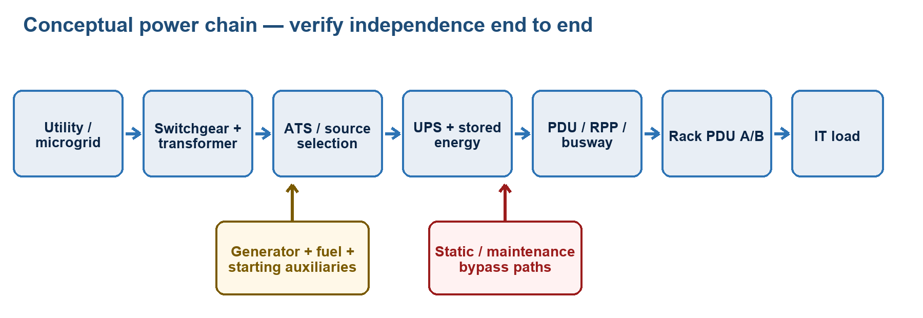
What mastery looks like
You can trace power from utility and on-site sources to a rack, calculate basic single- and three-phase quantities, explain each conversion/transfer/protection stage, and test whether redundancy survives maintenance and a credible fault. You can distinguish ATS from STS, grounding from bonding, kW from kVA, UPS topology from parallel configuration, and UPS batteries from a broader BESS. You size for real operating states, recognize power-quality and high-density constraints, and use thermography as a controlled diagnostic—not a substitute for maintenance.
Core concepts
Treat power as an end-to-end system. A typical chain is utility/microgrid sources → medium-voltage service/switchgear → transformer → low-voltage switchgear → ATS or other source transfer → UPS/energy storage and bypass → switchboard/PDU/busway/RPP → rack PDU → IT power supply. Actual order varies. At every stage ask about capacity, protection, isolation, monitoring, maintainability, physical separation and common controls.
Sustainability. Reduce demand before adding supply: right-size equipment, improve UPS/transformer efficiency at actual load, minimize distribution loss, improve cooling, measure stranded capacity and support IT utilization. PUE is total data-centre energy divided by IT-equipment energy under ISO/IEC 30134-2:2026 boundaries. Lower overhead does not prove low carbon, low water use or resilient operation. Evaluate energy source and time, emissions, water, refrigerants, embodied impact, battery/fuel lifecycle and heat reuse separately. Efficiency measures must be failure-tested; bypassing resilience to improve a headline ratio can increase business risk.
Microgrid. The U.S. DOE definition is a group of interconnected loads and distributed energy resources within clear electrical boundaries acting as one controllable entity with respect to the grid. Resources may include generators, solar, wind, fuel cells, combined heat and power and storage. A microgrid can operate grid-connected and, if designed, islanded. It needs controls, protection, synchronization, black-start strategy, load shedding, stable frequency/voltage, fuel/energy management and utility interconnection approval. A collection of rooftop PV and batteries is not automatically a microgrid; renewable generation is not automatically firm capacity during an outage.
Transformers. A transformer changes AC voltage and current through electromagnetic induction while frequency remains essentially unchanged. It can provide galvanic isolation and establish a separately derived neutral/earthing arrangement where code permits. Key concerns are kVA rating, impedance and available fault current, efficiency/losses, inrush, temperature rise, insulation, ventilation, tap settings, vector/phase shift, harmonics, neutral loading, noise, fire/environmental classification and maintainable isolation. Nonlinear IT/UPS loads can increase heating; select/design using actual harmonic spectrum rather than adding a label without analysis.
An isolation transformer has separate windings and provides galvanic isolation; it does not make hazardous voltage safe, eliminate all common-mode noise or replace protective grounding. Shielding and bonding details determine high-frequency behavior.
Generators. Engine generators bridge prolonged source loss after stored energy carries the load through start and transfer. Size and validate for steady kW/kVA, power factor, largest step load, motor/compressor starting, nonlinear loads, UPS rectifier behavior, altitude/ambient derating, emissions/noise, cooling, auxiliaries and post-fault configuration. Provide starting energy, heaters/chargers, lubrication/cooling, fuel quantity/quality, leak containment, ventilation/exhaust, fire protection and maintainable controls. Rating terms such as standby, prime and continuous have manufacturer/standard definitions; do not treat nameplate ratings as interchangeable. Exercise under meaningful load and test the full sequence; an unloaded monthly start does not prove the site will carry a black-building event.
ATS and STS. An automatic transfer switch (ATS) monitors sources and transfers a load between them, commonly using electromechanical switching. Open-transition ATS breaks before make; closed transition momentarily parallels acceptable synchronized sources and requires utility/protection approval. Transfer delay allows fault discrimination or generator stabilization. Bypass-isolation arrangements can enable ATS maintenance.
A static transfer switch (STS) uses power semiconductors to transfer a load rapidly between two compatible AC sources, often for sensitive single-cord loads. It generally needs sources within permitted voltage, frequency and phase conditions; an out-of-phase transfer can harm loads. An STS does not create energy, correct an overloaded downstream circuit or establish genuinely independent sources. IEC 62310 covers static transfer systems; IEC 62040 covers UPS.
Redundancy and topology. Define N as capacity required for the stated design load under stated conditions. N+1 has one additional unit; N+2 has two; 2N has two full-capacity systems; 2(N+1) has two full-capacity systems each with one spare unit. Distributed-redundant arrangements share reserve capacity across paths. These notations describe capacity, not automatically path independence, concurrent maintainability or fault tolerance.
Trace A and B to the load. Dual-corded IT should normally have each supply on a different independent path and be able to carry required operation after one path is lost. Single-cord equipment may need an STS or other qualified transfer solution. Verify capacity with one component/path unavailable, protective selectivity, bypass state, controls, room separation and maintenance isolation. A shared bus, bypass, battery, controller or procedural error can defeat impressive arithmetic.
Distribution and busbar trunking. Switchgear performs switching/protection at high fault duties; switchboards/panelboards distribute circuits; a floor PDU may combine transformer, breakers and metering; an RPP provides remote branch distribution; a rack PDU distributes receptacles at the rack. “PDU” is ambiguous—state the form. Rack PDUs may be basic, metered, monitored or switched; switching convenience must be access-controlled.
Busway/busbar trunking uses enclosed conductors with plug-in tap boxes, offering modular overhead or underfloor distribution and easy moves. Check current/voltage, neutral and protective conductor, short-circuit withstand, tap-box interlocks, phase balancing, thermal expansion, IP/environment rating, physical support, arc/maintenance safety and coordination. Flexibility does not remove the need for an approved load schedule.
Single- and three-phase. Single-phase supplies are common at branch/rack level. Balanced three-phase distributes power efficiently; phase-to-phase and phase-to-neutral voltage relationships depend on wye/delta arrangement. Keep phases balanced, account for neutral current from imbalance and triplen harmonics, and identify rotation for motors. Never infer voltage from “three phase” alone.
Grounding/earthing and bonding. Grounding/earthing intentionally connects a system or conductor to earth/reference under the adopted scheme. Bonding joins conductive parts to keep them at substantially equal potential and provide a low-impedance fault-current path. The equipment protective conductor must be deliberate and continuous. Neutral-to-ground bonding belongs only at code-defined points; extra downstream bonds can create objectionable current and unsafe touch conditions. Regional TN, TT and IT earthing systems differ. A separate “clean earth” that defeats protective equipotential bonding is unsafe; noise problems should be solved within a code-compliant coordinated bonding design.
PDU form factors and enclosure IP. Floor PDUs, RPPs, busway tap-offs and vertical/horizontal rack PDUs address different distribution levels. Check plug/receptacle type, phase, breaker poles, continuous-load requirements, cord locking, metering accuracy, remote communications, redundancy and overload alarm thresholds.
IEC 60529’s IP Code uses a first characteristic numeral for access/solid-object protection and a second for water. Higher numerals within each position generally indicate greater defined protection, but tests differ; X means not specified/tested, not zero. IP54 is not “better in every way” than every other enclosure, and North American NEMA enclosure Type numbers are not direct IP equivalents. Choose for dust, water direction/pressure, condensation, corrosion, heat removal and location.
Power quality. Monitor RMS voltage, frequency, interruptions, sags/dips, swells, transients, waveform distortion/harmonics, voltage/current imbalance, flicker where relevant, true power factor and grounding disturbances. A sag is a temporary RMS voltage reduction; a transient is a short-duration impulsive or oscillatory event. Harmonics arise from nonlinear loads and can heat neutrals, transformers and capacitors. Displacement PF concerns phase angle at the fundamental; true PF also includes distortion. Locate the disturbance by time-correlating meters along the chain; a single snapshot rarely proves cause.
Sizing. Start with measured or credible IT real/apparent power by rack and phase, workload diversity, growth and deployment schedule. Add network/storage and required mechanical/control/life-safety loads. At each upstream point include conversion loss, battery recharge, auxiliary power and the worst permitted maintenance/fault state; apply manufacturer deratings and local code rules for continuous loads, conductor ampacity and protection. Check both capacity and fault duty/coordination. Do not add redundant standby capacity as if it were extra sellable load.
HPC and AI loads. High rack density can require higher-current or higher-voltage distribution, busway, more connectors, close branch monitoring and liquid-cooling power. Assess fast load steps, power-supply harmonics, phase balance, peak versus sustained demand, coolant-distribution-unit/pump continuity, leak response and simultaneous loss/restart behavior. “Average rack density” hides local constraints; design by actual zone/rack and failure state.
UPS. IEC terminology classifies output dependency: VFD (voltage and frequency dependent, often called offline/standby), VI (voltage independent/line-interactive), and VFI (voltage and frequency independent, commonly double conversion). In a double-conversion UPS, rectifier/charger feeds a DC link and inverter; stored energy supports the link when input fails. A static bypass transfers to an alternate AC path under overload/fault/maintenance conditions; a maintenance bypass isolates the UPS for service. Bypass source compatibility, protection and common-mode exposure matter.
UPS arrangements include single, parallel capacity, parallel redundant and distributed/isolated-redundant or modular designs. In parallel, verify load sharing, circulating current controls, module isolation, common output/bypass, synchronization, battery configuration and capacity after one module is isolated. “Modular” improves serviceability only if modules, controls and bypass can be maintained without introducing a common failure.
Batteries. Common technologies include flooded lead-acid, VRLA, nickel-cadmium and lithium-ion families, each with different energy density, maintenance, gas/ventilation, temperature, monitoring, fire, environmental and cost characteristics. A battery system includes cells/modules, strings, racks/cabinets, disconnects/fuses, cabling, monitoring or a battery management system (battery BMS), charger and environment. Here battery BMS is distinct from the building management system used elsewhere in this guide. Capacity degrades with age, temperature history, discharge rate and cycling. Runtime must be calculated/tested at end-of-life design conditions, actual load, DC cutoff and inverter efficiency—not from nominal Ah alone.
Cells in series add voltage while Ah remains that of the string; equal parallel strings add Ah/current capability, but require balanced impedance and individual protection. A failed cell/string, loose intercell connection or open disconnect can remove autonomy even when float voltage appears normal. Monitor cell/block voltage, impedance/conductance where appropriate, temperature and connection condition; trend rather than rely on one threshold.
BESS. A battery energy storage system may serve peak shaving, renewable shifting, grid services, generator support or long-duration resilience as well as—or instead of—UPS ride-through. It typically adds a power-conversion system, a battery management system (battery BMS), an energy-management system, protection and site controls. Confirm whether it is grid-forming or grid-following, island-capable, black-start capable, and permitted to reserve enough state of charge for critical load. Thermal runaway, toxic/flammable gases, re-ignition, stranded energy and propagation require chemistry-specific prevention, detection, ventilation/explosion control, separation, suppression and emergency planning. In North American jurisdictions, consult the adopted NFPA 855/IFC and relevant UL 9540 system certification and UL 9540A test evidence; requirements and editions are jurisdiction-dependent.
Thermographic scanning. Infrared surveys can find abnormal thermal patterns in energized connections, breakers, bus joints, cables, transformers, UPS and batteries. Scan at meaningful stable load, record load/ambient conditions, use correct emissivity and reflected-temperature practices, compare similar phases/components and trend over time. Shiny metal can reflect a hot object; a cool component may simply be unloaded. Qualified personnel must follow electrical safe-work/arc-flash rules. A thermal anomaly triggers engineering investigation and safe corrective work; thermography neither proves correct torque nor authorizes opening energized equipment.
Key distinctions
| Pair | Correct distinction |
|---|---|
| kW vs kVA | kW is real power doing work/heat; kVA is apparent RMS volt-ampere loading. PF links them. |
| Power vs energy | kW is a rate; kWh is accumulated energy. |
| ATS vs STS | ATS is commonly electromechanical source transfer with longer transitions; STS uses semiconductors for rapid transfer between compatible AC sources. |
| N+1 vs 2N | N+1 adds a capacity unit; 2N duplicates full-capacity systems/paths. Neither notation alone proves independence. |
| Grounding vs bonding | Grounding references earth/system; bonding joins conductive parts into an equipotential low-impedance fault path. |
| Static vs maintenance bypass | Static bypass transfers electronically during operating conditions; maintenance bypass mechanically isolates the UPS for service. |
| UPS vs BESS | UPS prioritizes continuity/power quality to a protected load; BESS may perform broader energy/grid functions. One system can do both only if designed and validated. |
| UL 9540 vs UL 9540A | UL 9540 is a system/equipment safety standard; UL 9540A is a thermal-runaway fire-propagation test method, not a product listing by itself. |
Formulas and units where relevant
For DC or ideal single-phase resistive load, P = V × I. For AC single phase, S = V × I (VA) and P = V × I × PF (W). For a balanced three-phase system:
S = √3 × Vₗₗ × Iₗ, P = √3 × Vₗₗ × Iₗ × PF
Thus I = P/(√3 × Vₗₗ × PF) for a balanced three-phase load. Use consistent RMS units and include efficiency when sizing upstream input. In an ideal wye system, Vₗₗ = √3 × Vₗₙ; do not apply this blindly to delta arrangements.
PF = P/S. For sinusoidal quantities, P² + Q² = S², with reactive power Q in var. True PF under harmonics is not just cos φ.
Energy E = P × t: a constant 100 kW for 2 h uses 200 kWh. Ideal battery energy is approximately Vₙₒₘ × Ah, but usable AC energy is lower after discharge-rate, cutoff, aging, temperature and conversion effects.
Transformer ideal ratio: Vₚ/Vₛ = Nₚ/Nₛ and approximately Iₚ/Iₛ = Nₛ/Nₚ. Real transformers have losses and regulation.
Voltage THD is commonly THDᵥ = √(V₂² + V₃² + …) / V₁ × 100%. State harmonic range and measurement method.
Approximate required capacity before standard sizes is C ≥ design load / (derating factor × allowed-loading factor), then verify every normal, maintenance and fault state. Factors and continuous-load rules come from the adopted code and manufacturer, not a universal CDCP percentage.
Design and operations reasoning
Draw a one-line diagram, then highlight the active path in five states: normal utility; utility failure/start/transfer; one source or module under maintenance; one credible fault; restoration/failback. At each state calculate remaining kW/kVA/current, check protection and identify manual actions. Trace control power and monitoring communications too; a transfer device whose controller dies with the preferred source is not resilient.
For generator/UPS compatibility, validate the dynamic sequence: UPS stored energy takes load, generators start and stabilize, ATS transfers staged loads, rectifiers ramp while batteries recharge, cooling restarts, and the system withstands load steps without frequency/voltage collapse or repeated transfers. Integrated testing with safe load banks/simulations exposes interactions component tests miss.
For sustainability, compare lifecycle choices under the same service requirement. A high-efficiency UPS loaded at 10% may underperform a right-sized modular system, but aggressive module sleeping can reduce redundancy. Define a safe control envelope, alarms and automatic recovery, then measure actual energy.
Common traps
- Sizing only in kW while ignoring kVA, PF, harmonics, inrush and step load.
- Counting a standby redundant unit as normal usable capacity.
- Calling two utility feeds independent without shared-fate evidence.
- Assuming an isolation transformer eliminates all noise or protective earthing.
- Creating extra neutral-ground bonds or a “clean earth” isolated from safety bonding.
- Treating an IP numeral or NEMA Type as universally interchangeable.
- Calling a parallel UPS N+1 without capacity after one module, battery and bypass states.
- Estimating runtime directly from nameplate Ah with no aging, rate, cutoff or efficiency.
- Treating PV or BESS as available during outage without islanding, controls and reserved energy.
- Judging a thermogram by color alone without load, emissivity, reflections and comparable components.
Closed-book retrieval prompts
- Q: Give the balanced three-phase real-power equation. A: P = √3 × Vₗₗ × Iₗ × PF.
- Q: What does N+1 establish—and not establish? A: One capacity unit beyond N; it does not by itself prove path independence, concurrent maintainability or fault tolerance.
- Q: ATS versus STS? A: ATS transfers sources, usually electromechanically; STS uses semiconductors for rapid transfer between compatible AC sources.
- Q: Grounding versus bonding? A: Grounding references earth/system; bonding joins conductive parts into a low-impedance equipotential fault path.
- Q: What happens to voltage and Ah when identical cells are in series? A: Voltages add; string Ah remains one cell/string rating.
- Q: Name five UPS runtime inputs beyond nominal Ah. A: Actual load, end-of-life capacity, discharge rate, temperature, DC cutoff, inverter efficiency—any five.
- Q: Why might a BESS fail to support an outage despite stored energy? A: It may lack islanding/grid-forming or black-start capability, controls, permitted interconnection, or reserved state of charge.
- Q: What makes a thermographic finding defensible? A: Known load/ambient, correct emissivity/reflection practice, comparable components/trend, qualified safe access and follow-up diagnosis.
Module 7 — Electromagnetic Fields (EMF)
What mastery looks like
You can identify electric, magnetic and radiated fields; select the correct unit and instrument; distinguish personnel exposure from equipment EMC; locate likely data-centre sources; and choose source reduction, routing, separation or shielding appropriate to frequency. You do not promise that generic metal foil blocks 50/60 Hz magnetic fields or apply one exposure limit at every frequency.
Core concepts
Field types and frequency. Static fields do not vary with time. Power-frequency/ELF fields arise mainly at 50/60 Hz and harmonics. Radiofrequency fields cover wireless, broadcast and switching emissions at much higher frequencies. Electric and magnetic fields can be considered separately in low-frequency/near-field situations; farther from a radiating source they form an electromagnetic wave. Ionizing radiation has enough photon energy to ionize matter; the power-frequency and ordinary RF fields discussed here are non-ionizing. Do not use “radiation” alone to imply a health conclusion.
Units. Electric-field strength E is volts per metre (V/m). Magnetic-field strength H is amperes per metre (A/m). Magnetic flux density B is tesla (T), commonly microtesla (µT), or gauss (G)/milligauss (mG). Frequency is hertz (Hz); RF power density may be W/m². In simple free space B = μ × H, but material permeability and geometry matter.
Two different compliance questions. Human-exposure limits protect people and depend on frequency, exposure duration, occupational/public status and national adoption. ICNIRP and IEEE publish widely referenced guidance; national law/AHJ controls. Electromagnetic compatibility (EMC) concerns whether equipment emits excessive disturbance and remains immune enough to function; the IEC 61000 family and product standards are common references. A field can be below a human-exposure limit yet disrupt a sensitive device, and EMC conformity does not automatically prove every workplace exposure scenario.
Data-centre sources. Power cables/busways, poorly paired supply/return paths, transformers, switchgear, generators, motors, UPS/inverters, PDUs, battery conductors and high-current rack feeds produce low-frequency fields. Switching power electronics and variable-speed drives add harmonics/conducted emissions. Radios, phones, Wi-Fi, security systems and nearby transmitters produce RF. Large current loops, phase imbalance and distance are often more important than total kW.
Coupling mechanisms. Conducted disturbance travels on power/signal/ground conductors. Capacitive coupling is driven by changing voltage/electric fields; inductive coupling by changing current/magnetic flux through a loop; radiated coupling dominates when structures act as antennas. Mitigation must address the real coupling path.
Best-practice hierarchy. First reduce the source: correct imbalance, faults and unintended ground current; keep outgoing and return conductors together; minimize loop area; arrange phases symmetrically; use twisted pairs or appropriate cable geometry; and select low-emission equipment. Then increase distance and relocate sensitive equipment. Segregate power and signal routes, cross at roughly 90° where they must meet, and preserve cable shield termination/bonding design. Use shielding only after measurement and engineering.
Shielding is frequency-specific. A conductive, bonded enclosure is effective against electric fields and many RF fields when seams, doors, penetrations, ventilation and cable filters preserve continuity. Low-frequency magnetic shielding is harder: ordinary thin copper/aluminum foil may provide little attenuation at 50/60 Hz. Solutions may use distance, smaller/canceling current loops, phase arrangement or high-permeability material; such shields need specialist design because gaps, saturation, mechanical stress and installation can defeat them. Never add a shield that creates unsafe heating, fault paths or ventilation problems.
Measurement. Define the question, frequency range, quantity, averaging/peak method, load state and limit before selecting a calibrated instrument. Use an isotropic/three-axis probe where direction is unknown and frequency-selective equipment when source identification matters. Map repeatable points and heights, record three-axis result, load/current, equipment state, time, background, uncertainty and calibration. Measure representative high-load and abnormal configurations safely; one unlabelled “EMF reading” is not actionable.
Key distinctions
| Pair | Correct distinction |
|---|---|
| E field vs B/H field | Voltage/charge primarily produces electric field; current primarily produces magnetic field. Units and shielding differ. |
| Exposure vs EMC | Exposure protects people; EMC controls equipment emissions/immunity. Passing one does not prove the other. |
| Conducted vs radiated | Conducted energy travels on wiring; radiated energy couples through space. |
| Near field vs far field | Near the source E/H relation depends on source geometry; far-field waves have a predictable relationship. Do not use inverse-square blindly. |
| Source reduction vs shielding | Correcting current path/loop attacks cause; shielding is a frequency-specific barrier and usually later control. |
Formulas and units where relevant
Conversions: 1 T = 10⁴ G; 1 µT = 10 mG. For a long straight conductor in free space, B ≈ μ₀ × I/(2πr), showing current proportionality and distance reduction; real multi-conductor geometry can cancel or reinforce fields.
For a far-field wave, wavelength λ = c/f. Shielding effectiveness may be expressed as SE = 20 log₁₀[E(before)/E(after)] dB (likewise for comparable H), or 10 log₁₀[P(before)/P(after)] for power. A 20 dB field-amplitude reduction is a factor of 10, not 20%.
Design and operations reasoning
When a high reading or interference symptom appears: verify instrument/settings; correlate with load and switching state; map magnitude and frequency; trace conductors and return paths; correct imbalance, separation or loop geometry; remeasure; then evaluate engineered shielding if needed. Compare only with the correct frequency-dependent equipment criterion or jurisdictional exposure limit and document uncertainty.
Common traps
- Treating all EMF as one phenomenon with one unit or limit.
- Confusing gauss with tesla or µT with mG.
- Applying far-field inverse-square behavior beside a busbar/transformer.
- Buying “EMF paint/foil” for 50/60 Hz magnetic fields without measurement and engineering.
- Routing a supply far from its return, enlarging the current loop.
- Measuring at light load and declaring the high-load environment compliant.
- Assuming a personnel exposure limit guarantees equipment operation.
Closed-book retrieval prompts
- Q: Units for E, H and B? A: V/m, A/m and tesla respectively.
- Q: Convert 1 µT to mG. A: 10 mG.
- Q: Primary low-frequency magnetic-field source? A: Current and the geometry/area of its outgoing-return loop.
- Q: Exposure compliance versus EMC? A: Exposure protects people; EMC addresses equipment emissions and immunity.
- Q: Why keep supply and return conductors together? A: Their opposing fields partly cancel and the current-loop area is minimized.
- Q: First mitigation choice for elevated EMF? A: Identify/correct the source and current path, then use distance/routing before engineered shielding.
- Q: Why may copper foil disappoint at 50/60 Hz magnetic shielding? A: Low-frequency magnetic fields penetrate ordinary thin conductive shielding; geometry or high-permeability engineered solutions are usually needed.
- Q: What must accompany an EMF reading? A: Quantity/unit, frequency range, method, location/axis, load/state, time/background, calibration and uncertainty.
Authoritative source URLs and currency notes
- EPI, official CDCP R25 course syllabus and exam overview: epi-ap.com source
- TIA, ANSI/TIA-942-C announcement and scope (2024): tiaonline.org source
- TIA, certification types and Rated levels: tiaonline.org source
- ISO/IEC 22237-1:2021, general concepts: iso.org source
- ISO/IEC 22237-2:2024, building construction: iso.org source
- ISO/IEC 22237-3:2021, power distribution: iso.org source
- ISO/IEC JTC 1/SC 39 catalogue (current status of the 22237 series): iso.org source
- ANSI/BICSI 002-2024 and 009-2024 catalogue: shop.bicsi.org source
- Uptime Institute, Tier classifications and scope: journal.uptimeinstitute.com source
- U.S. Access Board, ADA ramp requirements (U.S. example only): access-board.gov source
- ISO/CIE 8995-1:2025, indoor workplace lighting: iso.org source
- ISO 30061:2007, emergency lighting: iso.org source
- U.S. OSHA 29 CFR 1910.37, exit-route lighting (U.S. example only): osha.gov source
- U.S. DOE, microgrid definition and concepts: energy.gov source
- ISO/IEC 30134-2:2026, PUE: iso.org source
- IEC 60529, enclosure IP Code: webstore.iec.ch source
- IEC 62040-3:2021, UPS performance/test requirements: webstore.iec.ch source
- NFPA 855, stationary energy-storage installation standard (confirm adopted edition): nfpa.org source
- UL Solutions, UL 9540 versus UL 9540A context and BESS testing: ul.com source
- WHO, electromagnetic-field overview and frequency-dependent exposure context: who.int source
- ICNIRP, current non-ionizing-radiation guidance catalogue: icnirp.org source
Use note. Standards are copyrighted and often paywalled. The summaries above identify concepts and scopes; they do not reproduce normative requirements. Before a real design, audit or exam-specific numeric recall, consult the authorized CDCP R25 courseware and the full, adopted standard/code edition. Drafts and proposed amendments are not compliance baselines unless a contract or authority explicitly says otherwise.
This material is an original study aid aligned to the publicly listed CDCP R25 outcomes. It explains concepts rather than reproducing EPI courseware or exam items. “Must” below means a sound engineering or operational principle unless a named standard or the authority having jurisdiction (AHJ) makes it mandatory. Numerical limits, inspection intervals, agent approvals, egress rules, electrical practices, environmental ranges, and water regulations are jurisdiction- and design-dependent; verify the adopted code, current standard edition, approved design, equipment documentation, and site procedures.
Module 8 — Equipment racks
What mastery looks like
You can translate an IT deployment into a rack specification that is mechanically safe, thermally compatible, serviceable, secure, and supportable by the room. You can explain why “19-inch” does not specify the cabinet’s outside width or depth; calculate usable vertical space in rack units; distinguish an open rack from an enclosed cabinet; choose mounting rails, doors, panels, cable management, bonding, anchorage, and rack power distribution; and identify how a rack choice can defeat airflow, redundancy, floor loading, or physical security.
Core concepts
Standards and dimensions. The IEC 60297 series covers mechanical structures in the 482.6 mm (19 in) family. One conventional rack unit, 1U, is 44.45 mm or 1.75 in high. A nominal 42U cabinet therefore has 1,866.9 mm (73.5 in) of mounting pitch, but its overall height is greater. “19-inch” describes the standardized equipment-mounting interface, not the external cabinet width, depth, door clearance, rail-to-rail depth, or load rating. Those must be checked separately. Open Compute racks use a different, wider equipment interface and an OpenU pitch; never assume interchangeability without the intended adapter and vendor approval.
Form factors.
- A two-post open frame is accessible and economical for suitable telecommunications equipment but has limited support for deep/heavy servers and little enclosure security or airflow control.
- A four-post open rack supports front and rear rails and deeper equipment, but the room provides the security and air boundary.
- An enclosed cabinet adds doors and side panels for security, airflow management, containment, and colocation demarcation. Doors and filters also add pressure drop and maintenance.
- Network cabinets tend to prioritize patching space, side access, and vertical cable management; server cabinets prioritize depth, weight, rails, front-to-back airflow, and high rack power. The labels are not substitutes for checking actual equipment.
Selection data. Build a rack elevation and capacity sheet. Check external dimensions; usable U; rail type and adjustment range; static, dynamic/shipping, rolling, and seismic load ratings; maximum permitted centre of gravity; door opening and perforation/free area; side-panel needs; cable entry; overhead or underfloor interfaces; liquid manifolds; containment interfaces; PDU space; grounding/bonding points; locks; sensors; and front/rear working clearance. Include servers, storage, switches, shelves, patch panels, rails, PDUs, cables, coolant, rear-door heat exchangers, and growth—not just chassis weight.
Airflow. Most server equipment is designed for front-to-rear flow. Align all intakes with the cold side and exhausts with the hot side. Correct side-to-side or rear-to-front devices with approved ducts, baffles, or a compatible layout. Install blanking panels in every unused U and seal cable openings so hot exhaust cannot recirculate to intakes. Keep cabling out of exhaust paths. A heavily perforated door is useful only when the entire air path—including filters, coils, cable bundles, and containment pressure—is adequate.
Mechanical safety. Confirm that the slab or access floor, pedestals, ramps, lifts, delivery route, and anchorage support the complete rack. Mount heavy equipment low where practical; use vendor rails; prevent a rack from tipping when equipment is extended; observe seismic requirements; and never use doors, PDUs, or cable managers as lifting points. A static load rating does not prove that a rack can be rolled while loaded or shipped populated.
Bonding. Bond metallic racks, doors, cable trays, and prescribed components to the telecommunications bonding network according to the site design. Bonding provides an intentional low-impedance equipotential path; it is not achieved merely because a rack sits on a conductive floor. Do not improvise protective-earthing conductors or remove listed bonding jumpers.
Rack power strips/rails (rack PDUs). Common capabilities progress from basic distribution, to aggregate input metering, to outlet-level metering, to remote switching, sometimes combining metering and switching. Vertical “0U” units preserve equipment U but require side space; horizontal units consume U. Select voltage, phase, plug/receptacle type, current and branch protection, outlet mix, locking/retention method, metering accuracy, communications, environmental rating, and A/B-feed compatibility. Dual-corded equipment should normally connect one supply to A and the other to B, with unmistakable labels and physically understood upstream independence. Remote switching helps recovery but adds cyber and accidental-shutdown risk.
Security. Decide the protection boundary: site, room, cage, cabinet, or individual device. Cabinet locks, tamper switches, door contacts, access logs, asset controls, and CCTV can supplement room controls. A generic keyed handle provides weak accountability. In shared environments use uniquely managed credentials/keys and control side/rear access as well as the front. Security must not block cooling, emergency release, fire detection/suppression, or safe service.
Key distinctions
| Pair | Distinction that matters |
|---|---|
| Rack vs cabinet | A rack is the supporting frame; a cabinet encloses it with doors/panels. Usage is sometimes loose, so inspect the specification. |
| 19-inch interface vs cabinet width | 482.6 mm is the mounting family; outside width is commonly larger and is separately specified. |
| U vs OU | Conventional 1U is 44.45 mm; Open Rack uses an OpenU and a different equipment interface. |
| Static vs dynamic/rolling load | Static is stationary capacity; moving, shipping, and seismic conditions impose different forces and ratings. |
| Basic vs metered vs switched rack PDU | Distribution only; measurement; and remote outlet control are different functions. “Intelligent” is too vague. |
| Grounding vs bonding | Grounding references earth/system ground; bonding intentionally equalizes conductive parts and provides a fault path. |
| Physical A/B diversity vs two labels | Two feeds are not resilient if they share a breaker, PDU, UPS, pathway, or other single failure point. |
| Device nameplate vs measured demand | Nameplate supports safety/provisioning; measured demand aids capacity planning but must not erase startup, peak, growth, or redundancy margins. |
Formulas/units where relevant
- Rack-unit height: height in millimetres = U × 44.45; height in inches = U × 1.75.
- Approximate IT heat released into the space: cooling load in kW ≈ IT electrical input in kW. Follow the actual heat-rejection boundary when some heat goes directly to liquid.
- Single-phase apparent power: S (VA) = V × I. Real power: P (W) = V × I × power factor.
- Balanced three-phase real power: P (W) = √3 × line-to-line V × line I × power factor. Use qualified electrical design data; this is not permission to load a branch circuit to its protective-device rating.
- Rack power density: rack kW = sum of simultaneous equipment demand under the design scenario. Divide by used U only if a per-U comparison is useful; the cooling system responds to the actual spatial load.
Example: 18U of installed equipment occupies 18 × 44.45 = 800.1 mm of mounting pitch. It does not imply an 800.1 mm-tall cabinet.
Design/operations reasoning
- Start with the IT bill of materials and failure scenario, not a favourite cabinet. Establish equipment sizes, weights, airflow directions, peak and steady power, connector types, cabling, liquid connections, and service method.
- Check the whole logistics chain: loading dock, doors, lift capacity, turns, floor/ramp rolling load, tile removal, final anchorage, and egress. A rack that fits the room may not reach it safely.
- Create rack elevations that reserve patching, switching, power and liquid distribution, cable bend radius, blanking, and growth. Keep heavy items low and frequently serviced items reachable.
- Model airflow and pressure. Verify intake conditions at equipment, not just room-average temperature. Seal bypass openings and correct recirculation before lowering supply temperature.
- Trace A and B power paths to independent upstream failure domains. Label both ends; phase-balance where applicable; set alarm thresholds below hard limits; and test metering and failover.
- Treat high-density AI racks as a system: cabinet load, slab/floor, busway, power whips, network density, manifolds/CDU, drip containment, leak detection, doors, and service clearances must all agree.
- Commission populated or representative racks: inspect torque/fastening per manufacturer, bonding, labels, doors, blanking, cable routing, sensor placement, airflow, power telemetry, access control, and alarm delivery.
- Maintain configuration control. A later side-flow switch, loose blanking panel, unlocked rear door, or cable bundle can invalidate the original thermal/security design.
Common traps
- Treating 19 inches as the cabinet’s external width.
- Equating 42U with the cabinet’s overall height.
- Checking only stationary weight while ignoring rolling, seismic, point, and delivery-route loads.
- Installing perforated doors but leaving open U positions and floor cut-outs that allow recirculation.
- Mixing airflow directions in one aisle without ducts or a documented exception.
- Assuming two rack PDUs mean true A/B resilience.
- Daisy-chaining power strips, defeating connector ratings, or using extension leads outside the approved design.
- Placing both power cords of a dual-corded server on the same feed.
- Using remote outlet switching without strong authorization, audit logs, and change control.
- Locking cabinets but leaving removable side panels, overhead access, shared keys, or exposed console ports uncontrolled.
- Applying a universal rack weight, door-open area, or branch-loading percentage. These are equipment-, standard-, and jurisdiction-dependent.
8 closed-book retrieval prompts with concise answers
- Prompt: What does “19-inch rack” standardize?
Answer: The equipment-mounting interface family; it does not by itself define outside cabinet width, depth, height, or load capacity.
- Prompt: Convert 12U to mounting height.
Answer: 12 × 44.45 mm = 533.4 mm, or 21 in.
- Prompt: Why install blanking panels?
Answer: To stop hot exhaust recirculating through unused U into equipment intakes and to preserve the intended pressure path.
- Prompt: What must be checked beyond static rack load?
Answer: Dynamic/rolling/shipping and seismic ratings, centre of gravity, floor and route loads, anchorage, and the weight of all accessories/cables/liquid.
- Prompt: How should a dual-corded server normally use A/B power?
Answer: One cord to A and one to genuinely independent B, with clear end-to-end identification.
- Prompt: What is the difference between a metered and switched rack PDU?
Answer: Metering measures load/energy; switching permits remote outlet control. A unit may do either or both.
- Prompt: Where should heavy equipment usually be mounted?
Answer: Low in the rack, consistent with service, airflow, rails, and vendor instructions, to reduce tip risk.
- Prompt: What is the best thermal measurement point?
Answer: At the IT equipment intake under representative operating conditions, not merely at a room thermostat.
Module 9 — Cooling infrastructure
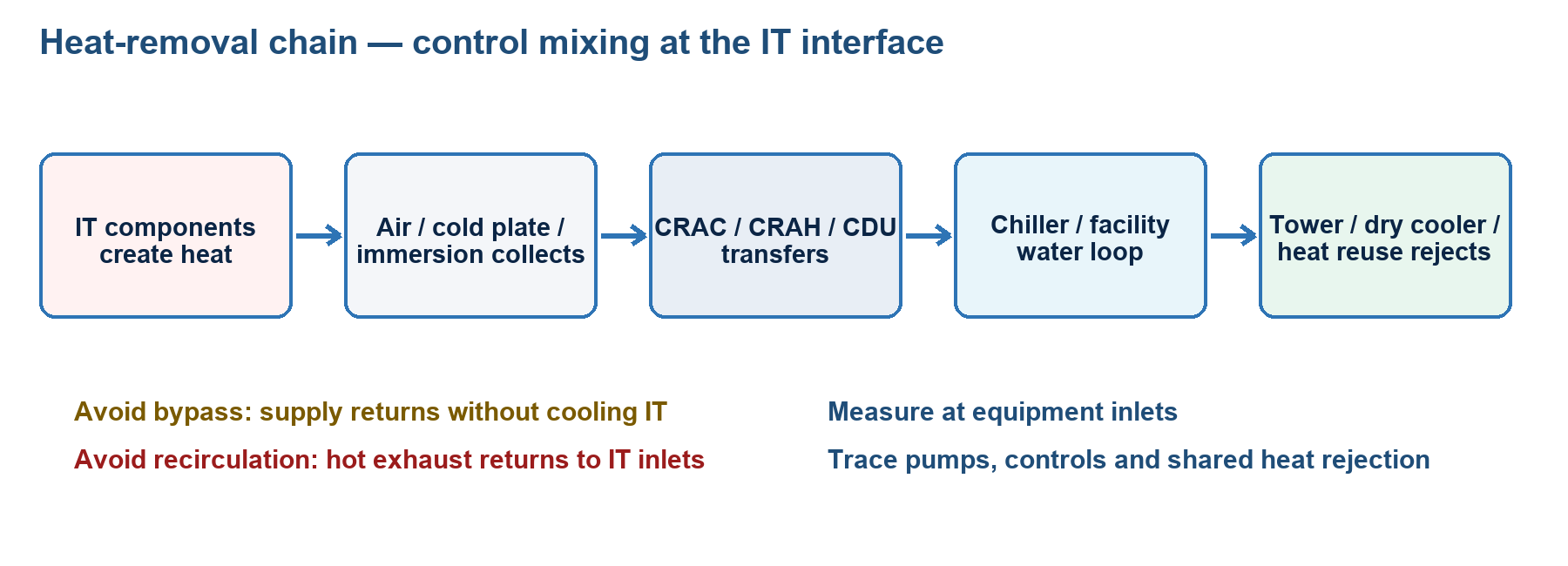
What mastery looks like
You can follow heat from the IT component to the outdoor environment, express load in common units, distinguish sensible from latent cooling and comfort from precision cooling, and reason about raised-floor, overhead, close-coupled, contained-air, direct-to-chip, rear-door, and immersion solutions. You can diagnose bypass air and recirculation, choose monitoring points, explain dew-point risk, and evaluate high-density/AI cooling, AI-assisted controls, redundancy, water use, and seasonal thermal energy storage without confusing efficiency with availability.
Core concepts
The heat path and thermal envelope. IT electrical energy becomes heat unless it leaves the chosen boundary by another path. Air cooling moves component heat through server/room air and coils to outdoor rejection; liquid cooling moves heat through a technology loop and CDU/heat exchanger to facility rejection. Design the entire path, including pumps, fans, controls, water, power, and failures.
Temperature and moisture. Protect each IT intake and vendor-specified liquid interface; room averages hide gradients/hot spots. RH is temperature-dependent, while dew point better predicts condensation: surfaces below local dew point can become wet. Excess moisture raises condensation/corrosion risk; very dry air can raise electrostatic risk. Use the actual equipment class and approved limits.
Sensible and latent heat. Sensible cooling changes dry-bulb temperature. Latent cooling removes moisture by condensation. Data halls usually have a high sensible heat ratio because IT generates mostly sensible heat and occupancy is low. Comfort systems are designed primarily for people, variable occupancy, and a larger latent component; precision/close-control systems are designed for continuous mission-critical operation, concentrated sensible load, controlled airflow, monitoring, and maintainability. The label alone does not prove capacity or resilience.
Air systems.
- CRAC commonly denotes a computer-room air conditioner with a direct-expansion refrigeration circuit; variants exist.
- CRAH commonly denotes a computer-room air handler using chilled water from central plant.
- Air-cooled or water-cooled DX, chilled-water plants, packaged units, evaporative/adiabatic systems, and air- or water-side economizers reject or avoid compressor heat in different ways.
- Raised-floor supply uses the underfloor as a pressurized delivery plenum; return may be overhead or through the room. Non-raised designs can supply overhead, at row level, or through ducts/plenums. A raised floor is not inherently more reliable or efficient.
- Close-coupled in-row, rear-door, overhead, or rack systems shorten the air path but add piping/leak, control, access, and failure dependencies.
Air management. Alternate rack fronts to form cold aisles and backs to form hot aisles. Three harmful paths are: recirculation (hot exhaust returns to an intake), bypass (cold supply returns without cooling IT), and leakage/mixing (the air boundary is lost). Correct these with rack orientation, blanking panels, sealed penetrations, managed tile/grille placement, adequate return paths, containment, and supply airflow matched to IT demand. More fan speed or colder air can mask rather than cure poor air management.
Containment. Cold-aisle containment encloses the cold supply aisle; the surrounding room becomes a warm return-air zone. Hot-aisle containment encloses hot exhaust; the surrounding room remains a cooler supply-air zone. Either can work. Selection depends on air distribution, ceiling height, work environment, leakage, pressure, equipment airflow, fire detection/suppression, lighting, egress, accessibility, and failure response. Coordinate containment with the AHJ; partitions may change sprinkler and detector coverage.
Capacity control and efficiency. Variable-speed fans/pumps, temperature reset, economizers, staged plant and good return temperatures reduce energy. AI-assisted control can forecast load, find anomalies, and optimize setpoints, but still needs calibrated sensors, hard limits, approved/fallback sequences, logs, cybersecurity, human override, and validation during unusual topology/weather.
High-density and liquid cooling.
- A rear-door heat exchanger transfers rack exhaust heat to liquid. Passive doors depend on server fans; active doors add fans/control. Neutral exhaust does not prove safe intakes.
- Direct-to-chip cold plates cool high-heat components; residual parts may need air. Hoses, quick disconnects, manifolds, flow, pressure, chemistry, materials, and leak response matter.
- A CDU controls and often hydraulically/chemically separates the facility water system (FWS) from the technology cooling system (TCS), maintaining flow, pressure, temperature, and fluid quality. CDUs may be in-rack, in-row, or central.
- Single-phase immersion keeps dielectric coolant liquid; two-phase boils it and condenses vapour. Check compatibility, containment/regulation, tank load, service, fire strategy, sampling, and disposal.
- Warm-water liquid cooling can increase economizer hours and heat-reuse potential. Supply must remain within IT limits and, where relevant, above dew point unless the system is engineered for condensation.
Redundancy. State capacity and topology, not just “N+1.” A redundant room unit is useless if all units share one failed pump, header, control panel, power source, water source, or heat-rejection path. Analyze both loss of a component and maintenance isolation. Thermal ride-through is finite: IT heat continues immediately after cooling loss, so alarms, response, load shedding, and orderly shutdown must match measured/modelled temperature rise.
Seasonal Thermal Energy Storage (STER). R25 labels the topic STER; industry normally abbreviates seasonal thermal energy storage as STES. UTES is the underground-storage family, including aquifer and borehole approaches. It stores heat or cold over weeks/months—for example, winter cold in a reservoir, aquifer or borehole for summer cooling—unlike diurnal chilled-water/ice storage. Evaluate geology, permits, groundwater, losses, pumping, thermal balance, redundancy, chemistry, capacity and lifecycle. Storage shifts production time; it is not an unlimited heat sink.
Key distinctions
| Pair | Distinction that matters |
|---|---|
| Heat vs temperature | Heat is energy transfer/load; temperature is a state. Equal temperatures do not imply equal heat loads. |
| Sensible vs latent | Sensible changes temperature; latent changes moisture/phase. IT load is predominantly sensible. |
| CRAC vs CRAH | CRAC usually includes DX refrigeration; CRAH usually uses chilled water. Confirm the actual design. |
| Supply temperature vs IT inlet temperature | Supply leaves cooling equipment; inlet is what the server receives after distribution and mixing. |
| Bypass vs recirculation | Bypass is supply air that misses IT; recirculation is exhaust that returns to intakes. |
| Cold- vs hot-aisle containment | One encloses supply; the other encloses exhaust. Both require pressure, fire, egress, and failure analysis. |
| Air economizer vs water economizer | One directly/indirectly uses favourable outdoor air; the other uses cool outdoor conditions to cool a water loop through heat exchange. |
| Direct-to-chip vs immersion | Cold plates cool selected components in a normal chassis; immersion places compatible IT in dielectric fluid. |
| FWS vs TCS | Facility water belongs to the building plant; technology cooling fluid interfaces with IT. A CDU commonly separates/controls them. |
| STER vs daily TES | Seasonal storage shifts heat/cold across months; chilled-water/ice storage commonly shifts within hours. |
| Temperature alarm vs control setpoint | A setpoint drives equipment; an alarm indicates unacceptable or risky state. They need deliberate separation/hysteresis. |
| Efficiency vs resilience | A low-energy solution can still have a shared single point of failure; both must be designed and tested. |
Formulas/units where relevant
- Heat rate: Q̇ = ṁ × cₚ × ΔT. Use coherent units. For water, cₚ is approximately 4.186 kJ/(kg·K); use the actual fluid properties and concentration.
- Air-side sensible approximation in SI: Q̇ (kW) ≈ 1.2 × airflow (m³/s) × ΔT (K) near standard conditions. Density/altitude and humidity change the factor.
- 1 kW = 3,412 Btu/h approximately.
- 1 refrigeration ton = 12,000 Btu/h = 3.517 kW approximately.
- Celsius/Fahrenheit: °F = (°C × 9/5) + 32; °C = (°F − 32) × 5/9.
- Sensible heat ratio: SHR = sensible cooling / total cooling. Total = sensible + latent.
- Coefficient of performance: COP = useful cooling output / input power. Higher is better under the same boundary/conditions.
- Cooling share must use the same measurement boundary and period when compared. Do not compare nameplate tons with measured IT kW without derating and system context.
Example: A liquid loop carrying 2 kg/s with a 5 K rise transports approximately 2 × 4.186 × 5 = 41.9 kW, before allowances and using water properties.
Design/operations reasoning
- Establish peak, typical, growth, transient, and failure-case heat by room, row, rack, and component. AI training clusters can combine high steady rack heat with rapid workload changes and dense network/power distribution.
- Identify the supported environmental class and vendor limits. Place calibrated sensors at representative rack intakes—bottom, middle, and top where appropriate—and in returns and liquid loops.
- Balance airflow. Compare IT airflow demand with delivered supply; eliminate open rack spaces and penetrations; verify pressure relationships; use smoke/thermal studies or CFD when risk/complexity warrants.
- Select architecture from heat density and site resources. Central air may suit moderate uniform loads; in-row/rear-door may address dense zones; direct liquid may be necessary when practical air volume or chip temperature becomes limiting.
- Trace all dependencies: electrical source, controls, communications, pumps, valves, headers, chillers/dry coolers/towers, make-up water, treatment, condensate, leak detection, and operator access.
- For liquid systems, agree interface control documents: temperatures, dew-point margin, flow, pressure, pressure drop, chemistry, filtration, materials, connections, alarms, ownership, isolation, drain/fill, and emergency response.
- Commission normal and abnormal modes. Test sensor failure, unit/pump/power loss, valve positions, containment doors, automatic restart, alarm escalation, leak detection, and thermal ride-through without putting production at uncontrolled risk.
- Optimize only after stabilizing airflow and instrumentation. Trend intake maxima, return temperature, fan/pump power, valve position, approach temperatures, cooling capacity, water use, and IT load together.
- Keep a safe fallback for AI-driven control. Bound every automatically adjustable variable, rate-limit changes, monitor model drift, retain deterministic emergency sequences, and document human override.
- Revalidate after moves/adds/changes. Cooling capacity in aggregate does not guarantee delivery to the new high-density rack.
Common traps
- Cooling to room-average temperature rather than protecting every supported IT intake.
- Treating RH as sufficient for condensation control while ignoring dew point and cold surfaces.
- Assuming a raised floor automatically delivers even airflow.
- Believing containment “creates cooling”; it improves separation but does not increase plant heat rejection by itself.
- Choosing hot- or cold-aisle containment without coordinating sprinklers, smoke detection, lighting, egress, or doors.
- Calling direct-to-chip “100% liquid cooled” when memory, power supplies, storage, and network devices still reject heat to air.
- Running cooling liquid below dew point without condensation controls.
- Counting N+1 terminal units while retaining a single pump, header, control, or heat-rejection point.
- Allowing an AI optimizer to cross manufacturer limits or suppress alarms for energy savings.
- Confusing seasonal storage with a short UPS-like cooling reserve.
8 closed-book retrieval prompts with concise answers
- Prompt: Why is IT electrical kW a useful first estimate of cooling load?
Answer: Nearly all IT electrical input becomes heat within the relevant facility boundary, except heat/energy explicitly leaving by another path.
- Prompt: What are bypass and recirculation?
Answer: Bypass is supply air returning without crossing IT; recirculation is hot exhaust re-entering IT intakes.
- Prompt: Why is dew point important in liquid cooling?
Answer: A pipe, cold plate, or connector below local dew point can condense moisture even when room RH appears acceptable.
- Prompt: What does a CDU do?
Answer: It controls the IT cooling loop and commonly heat-exchanges/separates it from facility water while managing temperature, flow, pressure, and fluid quality.
- Prompt: Contrast direct-to-chip and immersion.
Answer: Direct-to-chip sends coolant through cold plates on selected components; immersion submerges compatible equipment in dielectric fluid.
- Prompt: Does containment add cooling capacity?
Answer: Not inherently; it reduces mixing so existing airflow and coil/plant capacity are used more effectively.
- Prompt: What is STER?
Answer: Seasonal storage of useful heat or cold for later use, such as storing winter cold for summer cooling; it differs from daily ice/chilled-water load shifting.
- Prompt: What makes AI-assisted cooling safe?
Answer: Reliable sensors, hard operating limits, validated models, controlled change rates, audit logs, cyber controls, deterministic fallback, alarms, and human override.
Module 10 — Water supply
What mastery looks like
You can inventory every data-centre water use, distinguish withdrawal from consumption and closed-loop inventory from make-up, quantify site WUE, trace water loss in an evaporative system, and design a credible backup strategy tied to cooling and fire scenarios. You can explain why water quality, treatment, permits, drought, pumps, power, freeze protection, leak control, and testing matter as much as tank volume.
Core concepts
Where water is used. Potential uses include cooling-tower make-up, evaporative/adiabatic cooling, chilled-water and condenser-water loop filling/make-up, humidification, direct liquid cooling inventory, heat rejection, fire-protection storage, cleaning, sanitation, and landscape/office uses within the measurement boundary. A direct-to-chip closed loop may circulate a large volume but consume little in normal service; an open evaporative tower consumes water continuously. Do not equate flow through a loop with consumption.
Withdrawal, discharge, and consumption. Withdrawal is water taken from a source. Some may return to the watershed or sewer; consumption is the portion not promptly returned, often through evaporation or incorporation. Both matter to permits and community impact. Source water for electricity can also be relevant to a broader lifecycle metric even though site WUE focuses on on-site water.
Cooling-tower balance. Tower make-up replaces evaporation, blowdown, drift, and leaks. Evaporation rejects heat; dissolved minerals remain and concentrate. Blowdown deliberately removes concentrated water. Drift is entrained droplets carried out with air and should be minimized with eliminators. Cycles of concentration (CoC) express how concentrated recirculating water is relative to make-up. Raising CoC usually reduces blowdown and make-up, but scale, corrosion, microbiological control, discharge limits, and treatment establish the safe optimum.
Water quality. Chemistry affects scale, corrosion, erosion, biological growth, heat-transfer efficiency, valves, pumps, cold plates, seals, and warranties. Specify conductivity, pH, hardness, chlorides, dissolved oxygen, microbiological limits, filtration, inhibitor/biocide program, and compatible materials as required by the relevant loop and manufacturer. Facility water and a technology cooling loop often require different chemistry; the CDU prevents casual mixing. Sample and trend, not merely dose on a calendar.
Health and environmental controls. Cooling towers can aerosolize water and require a documented water-management program to control microbiological hazards such as Legionella. Chemical storage, discharge, plume/drift, noise, groundwater withdrawal, well injection, backflow prevention, and reclaimed-water use are governed locally. Jurisdiction-dependent: permits, testing frequency, responsible-person rules, discharge chemistry, potable separation, and reporting.
Reliability and backup. Translate the design event into demand and duration. A tank is only useful if it contains usable—not merely gross—volume; remains protected from contamination/freezing; has functioning level instruments, valves, pumps, power, treatment, and refill; and is connected through an approved arrangement. Options include dual utility feeds where genuinely independent, on-site storage, wells, reclaimed water, redundant treatment, truck connection, air/dry heat-rejection mode, load reduction, and controlled shutdown. A tanker contract is not resilience unless access, connector, quality, lead time, pumping, and simultaneous regional demand have been tested.
Fire water. Fire-protection water volume, pressure, pump power, replenishment, and separation are life-safety design matters. Do not borrow a protected fire reserve for cooling or assume a cooling tank satisfies fire code. The AHJ and fire engineer determine requirements.
Efficiency and trade-offs. Reduce load first through air management, higher allowable supply temperatures, economizers, efficient plant, and heat reuse. Optimize CoC, repair leaks/overflow, recover suitable condensate, and evaluate reclaimed/non-potable sources. Dry coolers and air-cooled chillers can reduce on-site water but may raise electrical energy, peak demand, noise, footprint, or hot-weather capacity. Compare water, energy, carbon, reliability, and local water stress together.
Key distinctions
| Pair | Distinction that matters |
|---|---|
| Withdrawal vs consumption | Withdrawal is taken from a source; consumption is not promptly returned, commonly because it evaporates. |
| Circulating flow vs make-up | Flow can be high in a closed loop while make-up/consumption remains low. |
| Gross tank volume vs usable autonomy | Dead volume, reserve, minimum suction level, quality, and operational constraints reduce usable water. |
| Evaporation vs blowdown vs drift | Evaporation performs heat rejection; blowdown controls concentration; drift is unintended droplets. |
| Site WUE vs source water impact | Site WUE counts water used at the site per IT energy; broader approaches can include water used to generate energy. |
| Potable vs reclaimed/non-potable | Alternative sources may save potable water but require compatible quality, treatment, identification, and lawful separation. |
| Cooling reserve vs fire reserve | They serve different risk and code purposes and must not be casually shared. |
| Water resilience vs a large tank | Resilience includes source, storage, quality, pumps, power, controls, connection, testing, and restoration. |
Formulas/units where relevant
- Site water usage effectiveness: WUE = annual site water use (litres) / annual IT equipment energy (kWh). Unit: L/kWh. Lower means less site water per IT energy for the same defined boundary; disclose boundary and period.
- Backup autonomy: hours = usable stored water / worst-case required make-up flow per hour. Include simultaneous uses and operating constraints.
- Tower make-up balance: M = E + B + D + L, where M is make-up, E evaporation, B blowdown, D drift, and L other loss, using consistent units.
- Simplified cycles of concentration: CoC ≈ concentration in recirculating water / concentration in make-up water, often estimated from a conservative ion or conductivity when treatment specialists approve.
- When drift and other loss are neglected, B ≈ E/(CoC − 1) and M ≈ E × CoC/(CoC − 1). Real systems require measured losses and chemistry.
- Liquid heat transport: Q̇ = ṁ × cₚ × ΔT. This calculates thermal transport, not water consumption.
Example: If annual site water use is 12,000,000 L and annual IT energy is 10,000,000 kWh, site WUE is 1.2 L/kWh. The result is meaningless for comparison unless boundaries and climates are understood.
Design/operations reasoning
- Make a water balance diagram from every source through treatment, storage, end use, recirculation, evaporation, discharge, and meter. Name ownership and the measurement boundary.
- Quantify normal, peak-design-day, maintenance, fire, leak, drought, and source-outage cases. Correlate meter data with IT load and weather.
- Determine cooling behavior during loss of make-up. Model tower basin levels, thermal storage, alternative heat rejection, pump availability, treatment limits, alarm lead time, and how quickly load must reduce.
- Size backup from usable volume and verified worst-case demand; reserve separate fire water as required. Validate refill time and whether refill is possible during the initiating event.
- Qualify each source for flow, pressure, quality, seasonality, regulatory permission, and common-mode risk. Two municipal connections may share the same main or treatment works.
- Provide meters at meaningful boundaries, redundant/validated level indication for critical tanks, water-quality instrumentation, low-pressure/low-flow alarms, and leak/overflow detection.
- Write and drill the water-outage response: confirmation, escalation, supplier callout, valve lineup, temporary connection, water-quality acceptance, load reduction, cooling transition, shutdown threshold, and recovery.
- Optimize with treatment specialists. Higher CoC is beneficial only within materials, chemistry, microbiological, and discharge limits.
- Track WUE with context: IT energy, weather, cooling hours, water source, water stress, commissioning/maintenance events, and data quality.
- Reassess for liquid-cooled AI deployments. Facility flow and inventory may rise, while consumptive use may fall or rise depending on the outdoor heat-rejection method.
Common traps
- Counting all loop flow as consumed water.
- Reporting WUE without the water/energy boundary or measurement period.
- Assuming lower WUE always means lower total environmental impact; energy source and local water stress can reverse priorities.
- Sizing backup from average day rather than the design outage at adverse weather/load.
- Using gross tank size in an autonomy calculation.
- Ignoring pump/control power during a utility outage.
- Treating two pipes from one municipal main as independent sources.
- Relying on an untested tanker agreement.
- Increasing cycles of concentration without chemistry, scale, corrosion, biological, and discharge analysis.
- Sending reclaimed water into a system without treatment/material/backflow checks.
- Sharing fire-protection reserve with cooling without AHJ-approved design.
- Assuming “liquid cooled” means water intensive or water free; heat-rejection architecture decides much of the consumption.
- Applying one universal storage duration, Legionella program, or fire-water quantity. These are design- and jurisdiction-dependent.
8 closed-book retrieval prompts with concise answers
- Prompt: What does site WUE measure?
Answer: Annual on-site water use divided by annual IT equipment energy, normally in L/kWh, for a stated boundary and period.
- Prompt: Name the four main tower make-up destinations.
Answer: Evaporation, blowdown, drift, and other losses/leaks.
- Prompt: Why is blowdown necessary?
Answer: Evaporation leaves dissolved solids behind; blowdown limits their concentration to control scale, corrosion, and related risks.
- Prompt: Why can a closed liquid loop have high flow but low water consumption?
Answer: The same fluid recirculates; only leakage, maintenance, or treatment losses require make-up.
- Prompt: What turns tank volume into credible autonomy?
Answer: Usable volume divided by worst-case demand, plus working pumps/power, lawful connection, correct quality, controls, access, refill, and tested procedures.
- Prompt: Why keep fire reserve distinct?
Answer: It is a protected life-safety resource sized and controlled under the AHJ-approved fire design, not discretionary cooling inventory.
- Prompt: What is the main CoC trade-off?
Answer: Higher cycles reduce blowdown/make-up but increase concentration-related scale, corrosion, and treatment/discharge challenges.
- Prompt: Can dry cooling lower water use without a downside?
Answer: It can lower on-site water, but may increase energy, peak power, noise, footprint, cost, or hot-weather limitations.
Module 11 — Designing a scalable network infrastructure
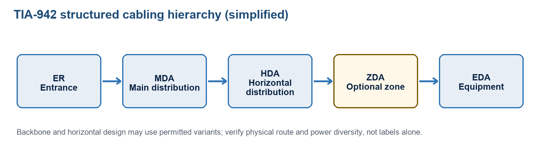
What mastery looks like
You can describe why structured cabling outlives active equipment, draw the TIA-942 functional-area hierarchy from carrier entrance to equipment rack, and distinguish a cabling topology from a logical switch fabric. You can select copper or fibre against application, reach, environment, density, power, and lifecycle needs; plan pathways and growth; explain ToR/MoR/EoR trade-offs; specify testing, labelling, administration, monitoring, and records; and prove that redundant links are physically diverse rather than merely drawn as two lines.
Core concepts
Structured cabling as infrastructure. Structured cabling is a standards-based system of permanent links, distributors/cross-connects, equipment cords, pathways, spaces, administration, bonding, and tests. It replaces uncontrolled point-to-point growth with repeatable interfaces. Active equipment may refresh every few years while pathways and installed cable may serve several generations, so plan bandwidth, fibre count, tray space, connector density, polarity, and modular expansion for the intended facility lifecycle.
Benefits include predictable performance, interoperability, easier change, testable links, and cleaner failure domains—but only while records and patch discipline stay current.
Plan before selecting media. Determine speed/ports, oversubscription, growth, routes, latency, availability, optics/polarity, remote power, environment, firestopping, access, and logical topology. Reserve cable, port, tray, cabinet, and cross-connect capacity while respecting fill, bend radius, pulling tension, weight, fire load, and separation.
TIA-942-C context. Published May 2024, it is the current TIA data-centre revision covering spaces/topologies, media, pathways, performance, administration, redundancy and more. Use the licensed adopted edition; other jurisdictions may use ISO/IEC or CENELEC systems and local codes.
Functional areas and cabling hierarchy. Learn the flow, while recognizing reduced and distributed designs:
- The entrance room (ER) supports carrier/access-provider entrance, protection, and demarcation. Diverse providers are not diverse if their outside-plant routes, ducts, building entrance, or upstream exchange are shared. “Entrance facility” is broader TIA-568 terminology; use the authorized R25/TIA-942 label in an exam item.
- The main distribution area (MDA) is the principal cross-connect/distribution point and commonly houses core/backbone switches and routers.
- An intermediate distribution area (IDA) is optional in larger or multi-floor facilities and distributes between the MDA and downstream areas.
- A horizontal distribution area (HDA) provides horizontal cross-connect/distribution toward equipment areas and commonly houses aggregation/access switching.
- An optional zone distribution area (ZDA) is a passive consolidation/interconnection point in horizontal cabling. It is not a convenient place for an undocumented active switch.
- The equipment distribution area (EDA) contains racks/cabinets and equipment outlets/connections serving IT equipment.
Backbone/distribution cabling interconnects upstream distributors; horizontal cabling serves EDAs from the relevant distributor, optionally through one designed consolidation point. Star topologies create managed central points. A smaller data centre may collapse functions into fewer spaces; collapsing does not remove the function, test, or documentation requirement.
Physical cabling topology versus logical network. TIA-942 functional areas describe physical infrastructure. Traditional three-tier core/aggregation/access, leaf-spine/fat-tree, full mesh, and other fabrics describe active connectivity. A leaf-spine fabric can be delivered over structured fibre that passes through MDA/HDA/EDA fields. Do not assume that one diagram answers both physical-route and packet-forwarding questions.
Switch placement.
- Top-of-rack (ToR) switches shorten server cords and reduce horizontal copper bulk, but multiply switches, management points, power ports, software instances, and stranded ports. “Top” is a role; the switch may be mounted elsewhere in the rack for airflow/service.
- End-of-row (EoR) or middle-of-row (MoR) centralizes access switching and can improve port utilization, but increases horizontal cable quantity, pathway congestion, and the blast radius of a switch or cabinet failure.
- A zoned/modular approach uses distribution points and pre-engineered trunks to scale pods. Choose based on port density, cable reach, failure domain, refresh model, airflow, power, operations, and economics—not fashion.
Copper. Balanced twisted-pair cabling supports standardized Ethernet and management/building applications and can deliver remote power. Category describes component/channel performance under a standard. Category 6A or better is a common current data-centre baseline where balanced copper is selected for 10GBASE-T channel capability, subject to the actual application and standard. Check channel versus permanent-link limits, patch-cord derating, bundling/temperature effects for power delivery, alien crosstalk, shielding/bonding needs, connector compatibility, and electromagnetic environment. Never infer supported speed from jacket colour.
Optical fibre. Multimode fibre offers cost-effective short-reach links with compatible optics; single-mode offers greater reach and a broad migration path, often at different optic economics. Select fibre type (such as a specified OM or OS category), wavelength, transceiver, connector, lane count, polarity, reach, insertion-loss budget, and future speed together. More fibre strands provide migration and resilience only if pathways, panels, polarity maps, and records keep them usable. High-density multi-fibre connectors need rigorous polarity and end-face control.
Pathways and spaces. Separate diverse A/B paths far enough that one event cannot sever both. Protect bend radius and pulling limits; provide accessible trays, underfloor routes, conduits, sleeves, and firestops; separate telecommunications from power as the applicable code/standard and electromagnetic assessment require; avoid water hazards and hot exhaust; and maintain penetration ratings. Cable-above-cable redundancy in one tray is not diversity.
Administration. Apply the current project labelling/administration standard (for example, ANSI/TIA-606 in TIA projects). Use unique, durable identifiers at both ends and map them to building, room, pathway, rack, panel, port, cable, fibre/pair, and service records. Maintain patch schedules, as-builts, test results, splice maps, polarity, reserved capacity, and ownership. Labels must match records after every move/add/change.
Testing and verification.
- Visually inspect copper workmanship, terminations, pathway, labels, separation, bonding where applicable, and firestopping. Certify the installed link/channel to the selected category and configuration using a suitable calibrated field tester and correct adapters. Typical parameters include wire map, length, insertion loss, return loss, delay/skew, near-end crosstalk and related crosstalk metrics.
- For fibre, inspect and clean every end face before connection/test. Verify continuity, polarity, length, and insertion loss with an optical loss test set using the correct reference method, wavelength, and test reference cords. An OTDR characterizes events, distance, reflectance, splices, and faults; it does not automatically replace an end-to-end loss test.
- Compare results to the specified limit and loss budget, not to “link up.” Save native result files and summary records tied to cable IDs. A passing switch link may still have no margin for the next speed.
Redundancy and site-to-site connectivity. Identify required provider, entrance, pathway, room, rack, panel, switch, line-card, transceiver, power, and fibre diversity. Seek geographic route diversity between sites, not merely different carrier invoices. Confirm demarcation, service-level objectives, capacity, latency, encryption/security, routing convergence, out-of-band management, spare optics/fibres, DDoS exposure, and restoration priorities. Test failover and degraded capacity; redundancy that has never been exercised is an assumption.
Network monitoring. Beyond ping, monitor flaps, utilization/microbursts, discards/errors, CRC/FEC, optical levels, latency/jitter/loss, routes, power/environment, configuration, capacity and telemetry gaps. Synchronize time, baseline, retain logs, protect management, and use genuinely independent out-of-band access.
Key distinctions
| Pair | Distinction that matters |
|---|---|
| Structured vs point-to-point cabling | Structured cabling uses managed permanent links/distributors; point-to-point directly connects equipment and becomes difficult to scale at distance/density. |
| Physical vs logical topology | Rooms, pathways and cable links are physical; leaf-spine, routing, VLANs and failover are logical/active. |
| MDA vs HDA | MDA is the principal distribution/core point; HDA distributes horizontal connectivity toward EDAs. |
| IDA vs ZDA | An IDA is an optional intermediate distribution area in the backbone hierarchy and may contain cross-connects and active equipment; a ZDA is a passive consolidation point in horizontal cabling. |
| Backbone vs horizontal cabling | Backbone connects distributor levels/entrance; horizontal connects the relevant distributor to equipment areas, optionally through a designed zone point. |
| ToR vs EoR/MoR | ToR reduces server cable reach but multiplies switches; EoR/MoR centralizes switching but increases cabling and failure concentration. |
| Multimode vs single-mode | Different fibre/optic systems with different reach, bandwidth, connector/optic economics, and migration characteristics. |
| OLTS vs OTDR | OLTS measures end-to-end insertion loss; OTDR locates/characterizes events along fibre. They answer different questions. |
| Redundancy vs diversity | Redundancy adds another component/link; diversity removes shared physical and organizational failure points. |
| Link-up vs certification | Link-up proves current devices communicate; certification proves defined cabling performance/margin against a standard. |
Formulas/units where relevant
- Fibre link-loss budget: calculated channel insertion loss = cable attenuation + connector losses + splice losses, all in dB. Verify that calculated loss plus design margin is no greater than the applicable channel-loss limit or optical power budget.
- Power ratio in decibels: dB = 10 log₁₀(P₂/P₁). A negative change indicates loss under a stated direction.
- Utilization: transmitted bits per second / usable interface rate × 100%. A low interval average can hide microbursts.
- Oversubscription ratio: aggregate downstream demand or port capacity / available upstream capacity, with assumptions stated. It is not automatically bad; it must fit workload and failure-mode demand.
- Availability of links cannot be safely computed by multiplying assumed probabilities if routes share a common failure. Map common causes first.
- Copper and optical maximum distances are application-, media-, connector-, temperature-, and topology-specific. Use the governing application and cabling standard rather than one memorized universal reach.
Design/operations reasoning
- Convert compute/storage demand into port, bandwidth, latency, oversubscription, and failure-mode requirements by rack, pod, hall, and site.
- Draw two diagrams: the logical fabric and the physical TIA-942 spaces/pathways. Then mark every common failure point where the diagrams converge.
- Select ToR, MoR/EoR, or zoned placement based on cable volume, port utilization, switch count, airflow, failure domain, refresh practice, and operator capability.
- Choose copper/fibre and connectors from the application roadmap and total loss/reach budget. Decide polarity and migration method before ordering trunks.
- Size pathways, cabinets, panels, ports, and fibre count for current installation plus staged growth, while retaining bend radius, access, firestopping, and cooling.
- Establish A/B carrier entrances, routes, rooms, trays, panels, switches, transceivers, and power where availability requires them. Obtain route evidence; carrier names are not proof.
- Create labels and records before installation. A cable ID should connect the physical cable, test file, patch record, endpoints, route, owner, and service.
- Inspect, certify, remediate, and baseline before service. Clean fibre before every mating; keep proof of the reference method and tester calibration.
- Commission link, device, path, and site failures. Observe convergence, application impact, remaining capacity, alarms, out-of-band access, and restoration.
- Trend capacity and errors so expansion occurs before congestion. Review after every major move/add/change and reconcile the physical record.
Common traps
- Confusing the TIA-942 cabling hierarchy with a leaf-spine logical fabric.
- Swapping MDA, HDA, ZDA, and EDA roles.
- Putting an active switch in a passive ZDA without redesign/documentation.
- Assuming two carriers are diverse without route and entrance evidence.
- Routing A and B in one tray, sleeve, bridge, or manhole.
- Selecting fibre only by colour or “multimode versus single-mode” without optic, reach, loss, wavelength, polarity, and lifecycle.
- Treating an OTDR trace as a substitute for end-to-end insertion loss.
- Testing dirty fibre; contamination can damage end faces as well as add loss.
- Accepting “link up” instead of standards-based certification and retained results.
- Ignoring power delivery heat in copper bundles.
- Monitoring device reachability but not errors, optical margin, latency, congestion, route changes, telemetry health, or configuration drift.
- Applying TIA revision-specific cabinet widths, cable categories, distances, or firestop rules without checking the adopted edition and local code.
8 closed-book retrieval prompts with concise answers
- Prompt: Put the common TIA-942 functional areas in order from carrier to server.
Answer: Entrance room → MDA → optional IDA → HDA → optional passive ZDA → EDA, with reduced/distributed variants possible.
- Prompt: What is the MDA?
Answer: The principal distribution/cross-connect point, commonly associated with core/backbone switches and routers.
- Prompt: What makes a ZDA different from an IDA?
Answer: A ZDA is an optional passive horizontal consolidation point; an IDA is an optional intermediate distributor in larger backbone hierarchies.
- Prompt: Why separate physical and logical diagrams?
Answer: A resilient logical fabric can still share one tray, room, panel, power source, or carrier route.
- Prompt: What is the main ToR trade-off?
Answer: Shorter server cabling and less horizontal bulk, but more switches, management, power, software, and potentially stranded ports.
- Prompt: What two basic fibre tests answer different questions?
Answer: OLTS gives end-to-end insertion loss; OTDR locates and characterizes events along the fibre.
- Prompt: Why is “link up” insufficient acceptance?
Answer: It proves only that current endpoints communicate, not that the installed cabling meets its category/loss margin, documentation, or future application requirement.
- Prompt: What proves carrier diversity?
Answer: Verified separation of providers’ upstream networks, geographic routes, ducts/manholes, building entrances, rooms, equipment, power, and restoration dependencies as required.
Module 12 — Fire protection
What mastery looks like
You can reason from fuel, ignition, oxygen, detection, control, evacuation, suppression, and recovery as one life-safety system. You can identify common data-centre ignition sources, distinguish smoke/heat detection and water/gaseous suppression choices, explain staged detection and total-flooding prerequisites, select the correct portable-extinguisher class for the jurisdiction and energized state, and recognize that continuity goals never override occupant and responder safety or the AHJ-approved fire strategy.
Core concepts
Fire model and prevention. The fire tetrahedron comprises fuel, heat, oxidizer, and the sustaining chemical chain reaction. Prevention removes or controls these elements: minimize combustible packaging and storage; use listed equipment; maintain clean electrical connections and protective devices; prevent overloaded/loose conductors; control hot work; segregate fuels and chemicals; manage batteries; keep filters/plant clean; seal penetrations correctly; and enforce housekeeping. Common data-centre sources include electrical faults, overheating components and cables, UPS/battery failures, generator/fuel plant, mechanical equipment, hot work, and combustibles stored in technical spaces.
Layered protection. Combine prevention, early detection, alarm, compartmentation/firestopping, suppression, approved power/HVAC sequences, evacuation, responder access, and recovery. Clean agent cannot compensate for failed firestops, housekeeping, or response.
Detection.
- Spot-type smoke detectors detect smoke at installed locations. Photoelectric and other listed technologies have different response and nuisance characteristics.
- Air-sampling/aspirating smoke detection continuously draws samples through a pipe network to a detector and can provide very early warning with multiple alarm levels. Sampling-port layout, transport time, filtration, airflow, sensitivity, maintenance, and commissioning determine performance.
- Heat detectors respond to fixed temperature or rate-of-rise and can suit harsher locations but normally warn later than smoke detection for a smouldering electronics event.
- Detection locations must reflect airflow and hazards: ceiling, return/exhaust paths, underfloor/ceiling plenums with combustibles, containment zones, cabinets, battery/plant rooms, and other spaces as the approved design requires. High airflow can dilute or carry smoke away from a casually placed detector.
Use staged alarm logic where designed: an early alert prompts investigation; a confirmed condition may initiate evacuation, shutdown/interlocks, and agent release. Cross-zoning can reduce unwanted discharge by requiring corroborating detection, but logic must not delay required life safety. Exact sequences are jurisdiction- and design-dependent.
Water-based suppression.
- Wet-pipe sprinklers contain pressurized water and are simple, reliable, and fast once an individual head operates from heat. Water is not released merely because a smoke detector alarms.
- Dry-pipe sprinkler piping contains pressurized air/nitrogen downstream of a valve that holds back the water supply; it is used where freezing is credible. Complexity and delivery delay make it unsuitable as a generic “safer for electronics” choice.
- Pre-action piping is normally dry and has supplemental detection. In common arrangements, a single-interlock valve opens on detection; a non-interlock valve can open on detection or automatic-sprinkler operation; and a double-interlock valve requires both detection and sprinkler/air-loss conditions. Water discharges only from opened sprinkler(s). The exact listed and approved sequence governs. Pre-action can reduce some accidental water-release risk but adds detectors, valves, controls, supervision, maintenance and failure modes.
- Water mist uses fine droplets and a listed, hazard-specific design. It is not interchangeable with a conventional sprinkler system.
Gaseous/total-flooding suppression.
- Clean halocarbon agents commonly suppress through heat absorption and chemical/physical effects; inert-gas systems reduce oxygen concentration. Both require a listed agent/system and hazard-specific concentration.
- Carbon dioxide can suppress effectively but presents severe asphyxiation risk and is not treated as an occupant-friendly clean-agent substitute.
- Total flooding needs an enclosure that retains concentration for the required period. Conduct room-integrity testing and manage penetrations, dampers, door closers, pressure-relief venting, HVAC/airflow shutdown or recirculation sequence, underfloor/ceiling volumes, reserve cylinders where required, and post-discharge ventilation.
- Provide approved detection/release logic, supervised circuits, manual release/abort functions if required, pre-discharge audible/visual alarms, signage, evacuation delay, emergency procedures, and responder controls. Exact configuration is set by the listed design, agent exposure limits, code, and AHJ.
- Agent environmental acceptability changes. Check ozone/climate effects, breakdown products, supply/phase-out, and local regulation at design/refill. “Clean” does not mean harmless to people or climate.
Power and airflow interfaces. Fire alarm actions may stop supply/return fans, close dampers, release doors, unlock egress, send elevators to a safe mode, isolate selected power, or trigger an emergency power-off sequence. These actions are not universal. Abrupt EPO can harm continuity and responders if poorly coordinated; continued high airflow can dilute a gaseous agent. Use the approved cause-and-effect matrix and test it end-to-end.
Fire classes and portable extinguishers. Classification varies. In the United States, Class A covers ordinary combustibles; B covers flammable or combustible liquids, flammable gases, greases and similar materials; C covers energized electrical equipment; D covers combustible metals; and K covers cooking media. In many European/international schemes, Class C refers to flammable gases, Class F to cooking oils, and electrical risk is marked separately rather than a fire class. Jurisdiction-dependent: use the local classification, approved extinguisher type, travel distance, mounting, inspection, and training rules. For energized electrical equipment choose a nonconductive agent approved for that hazard; once safely de-energized, classify the underlying fuel. Only trained/authorized persons should fight an incipient fire when safe; otherwise alarm, evacuate, and call responders.
Signage and human safety. Mark exits, release/abort, extinguisher and gas hazards, alarm meaning, EPO and restricted controls as required. Keep access clear; drill evacuation, accountability, assistance, responder liaison, and re-entry authority.
Inspection, testing, and impairment. Fire protection degrades silently. Test the full detection, alarm, interface, water/gas, enclosure, door/damper, extinguisher, power and communication chain at required intervals. Authorize impairments, assess risk, notify, compensate, time-limit, restore/test, and record.
Key distinctions
| Pair | Distinction that matters |
|---|---|
| Detection vs suppression | Detection finds/annunciates fire signatures; suppression controls/extinguishes fire. One does not replace the other. |
| Smoke vs heat detection | Smoke commonly gives earlier warning; heat is generally later but may suit environments prone to smoke-detector nuisance. |
| Aspirating vs spot smoke | Aspirating transports sampled air and can stage very early alerts; spot detectors sense at their installed point. Both require airflow-aware design. |
| Wet-pipe vs pre-action | Wet-pipe piping already contains water; pre-action piping is normally dry and admits water under the listed release logic. Single-, non- and double-interlock arrangements use different detection/sprinkler or air-loss conditions. |
| Sprinkler operation vs smoke alarm | A standard sprinkler head opens from local heat; a smoke alarm alone does not make every sprinkler discharge. |
| Clean halocarbon vs inert gas | Halocarbon agents largely absorb heat; inert agents reduce oxygen. Storage volume, pressure, venting, exposure, and environmental profiles differ. |
| Clean agent vs CO₂ | CO₂ has significant life-safety hazard and is not equivalent to an occupied-space clean-agent design. |
| Local application vs total flooding | Local systems protect a defined object/area; total flooding establishes concentration throughout an enclosure. |
| Alarm acknowledgment vs safe condition | Acknowledgment only records operator receipt; the hazard remains until investigated, cleared, and reset under procedure. |
| US Class C vs European Class C | US C means energized electrical equipment; in common European schemes C means flammable gas. Always apply the local scheme. |
Formulas/units where relevant
Agent sizing is specialist work. Concentration, cylinders, hydraulics, detector spacing, pressure relief, hold/exposure limits and extinguisher placement require the listed system, adopted standard, room conditions, hazard and AHJ.
Useful conceptual quantities:
- For gaseous agents, volume concentration (%) = agent gas volume / total gas-mixture volume × 100 at stated conditions. Stored agent mass and cylinder quantity require the agent-specific listed sizing equations.
- Enclosure net volume must consider protected underfloor/ceiling spaces and fixed contents as the relevant standard directs.
- Backup/hold performance is not proven by cylinder pressure alone; enclosure integrity and airflow state control retention.
- Detector response in an air-sampling system includes smoke transport time plus detector response and programmed verification.
Design/operations reasoning
- Perform a fire risk assessment by space: data hall, cable plenum, battery room, UPS/switchgear, generator/fuel, loading/storage, office, and cooling plant have different fuels and consequences.
- Prevent ignition and fuel accumulation through maintenance, protection coordination, housekeeping, hot-work permits, battery monitoring, cable control, and fire-rated compartmentation.
- Map airflow and containment before locating detection. Provide early-warning and confirmed-fire levels appropriate to response capability.
- Select suppression as a layered system. Decide how sprinklers, pre-action, clean agent, cabinet/local protection, and portable extinguishers interact; do not choose solely to avoid cleanup.
- Produce a cause-and-effect matrix for every detector level, manual station, supervisory event, agent release, fan/damper, door, EPO, notification, and remote signal.
- Validate total-flooding boundaries: enclosure leakage, pressure relief, damper/door action, protected volumes, obstructions, agent distribution, exposure, and post-discharge ventilation.
- Coordinate containment changes with the fire engineer and AHJ. Roofs/doors can create new compartments or block detection and discharge distribution.
- Commission with integrated tests—not isolated device checks. Verify the alarm reaches occupants, responders, monitoring staff, controls, and event records in the intended sequence.
- Drill safe decisions: investigate only under procedure; do not prop doors; evacuate at the required alarm; account for people; never re-enter because IT service appears critical.
- Control impairments and modifications. A cable penetration, open damper, disabled detector, missing cylinder, or unreported construction dust can defeat the system.
Common traps
- Prioritizing equipment protection over evacuation and responder safety.
- Assuming smoke detectors directly discharge ordinary sprinkler heads.
- Calling pre-action “dry pipe” or assuming it has fewer failure modes than wet pipe.
- Choosing gaseous suppression without room-integrity testing, pressure relief, or HVAC coordination.
- Assuming “clean agent” means nontoxic, environmentally benign, or safe at any concentration.
- Using CO₂ in an occupied-space concept without recognizing its asphyxiation hazard.
- Ignoring underfloor, ceiling, containment, and cable-return airflow in detection/suppression design.
- Applying US fire-class letters globally.
- Using a portable water extinguisher that is not listed/approved for energized electrical equipment, or using the wrong agent on batteries/metals without hazard-specific guidance. Fixed sprinklers and water-mist systems follow their listed, AHJ-approved design.
- Disabling alarms/suppression for maintenance without formal impairment control.
- Memorizing agent concentration, hold time, detector spacing, or extinguisher travel distance without the system, code edition, and jurisdiction.
8 closed-book retrieval prompts with concise answers
- Prompt: Name the four elements of the fire tetrahedron.
Answer: Fuel, heat, oxidizer, and sustaining chemical chain reaction.
- Prompt: Why is aspirating detection useful in a data centre?
Answer: It actively samples air and can provide staged very-early warning, if pipe layout, airflow, sensitivity, and maintenance are correctly engineered.
- Prompt: Does a smoke alarm normally open a wet-pipe sprinkler head?
Answer: No. An individual sprinkler normally opens from local heat; smoke detection performs alarm/control functions.
- Prompt: What is the purpose of pre-action?
Answer: It keeps piping normally dry and adds supplemental detection/release logic, reducing some accidental-release risk while adding complexity. Single-, non- and double-interlock sequences differ, so learn the approved design rather than one universal valve rule.
- Prompt: What must a total-flooding design control besides agent quantity?
Answer: Enclosure integrity, airflow/dampers, discharge distribution, pressure relief, hold time, exposure/evacuation, alarms, controls, and ventilation.
- Prompt: Why is CO₂ not an occupied-space clean-agent equivalent?
Answer: Extinguishing concentrations can create a severe asphyxiation hazard.
- Prompt: What does US Class C mean, and why is that a trap?
Answer: Energized electrical equipment; other schemes use C for flammable gas, so local classification governs.
- Prompt: What should happen during a fire-system impairment?
Answer: Authorize and assess it, notify affected parties/AHJ as required, apply compensating measures, limit duration, restore/test, and document.
Module 13 — Physical security and safety
What mastery looks like
You can build risk-based layers from the site boundary to the rack, connect detection and delay to a credible response, administer identities/visitors/keys and surveillance evidence, and resolve security controls against emergency egress and worker safety. You can recognize principal data-centre hazards and apply the hierarchy of controls, permits, isolation, PPE, training, drills, and incident learning. You never treat a lock, camera, or “mantrap” as a complete system.
Core concepts
Risk and layers. Identify assets, threats, vulnerabilities, likelihood, consequence, and existing controls. Apply concentric zones—public approach, property perimeter, building, operations areas, data hall, cage, cabinet/device—as the risk warrants. Each layer should deter, detect, delay, support assessment/response, and preserve evidence. A fence or locked door that delays an intruder for 30 seconds is ineffective if no one receives the alarm for 20 minutes.
Physical controls. Possible controls include site selection/setback; hostile-vehicle mitigation; fencing, gates, lighting and clear sightlines; guards; intrusion/door/duress alarms; access-controlled doors and vestibules; CCTV; secure loading and delivery inspection; cages/cabinets; locks and tamper evidence; and secure media/asset movement. Design against tailgating, door propping, shared credentials, roof/utility/loading access, removable panels, and insider misuse. Do not create blind spots or obstruct exits, fire equipment, cooling, accessibility, or responders.
Identity and access. Grant named people least-privilege access to defined zones and time windows based on approved business need. Verify identity before credential issue; separate requester/approver where warranted; protect badge stock, keys, PINs and biometric templates; log use; review rights; and revoke promptly on termination, role change, expiry, loss, or compromise. A biometric is an identifier, not a secret; combine factors where risk justifies it and provide a controlled fallback.
Visitors, contractors and deliveries. Pre-authorize, verify identity, issue visibly distinct expiring credentials, brief rules, limit destinations/tools/devices, escort as required, log entry/exit, and recover credentials. Control after-hours work and temporary access. Chain of custody should cover incoming equipment and outgoing assets/media; “known courier” is not authorization.
Access-control vestibules. An interlocked vestibule can resist tailgating and enforce one-person flow; avoid the casual term “mantrap” in formal design. Provide lawful accessibility, occupancy sensing, duress/emergency release, fire-alarm interface, fail-safe/fail-secure behavior, and procedures for entrapment and evacuation. Jurisdiction-dependent: egress and door release always follow the fire/building code and AHJ.
CCTV. Design cameras for a purpose—detection, assessment, identification, route tracking, or evidence. Check field of view, pixel density, lighting/backlight, frame rate, placement, time synchronization, tamper detection, health monitoring, retention, export, access and privacy. A camera is not preventive if nobody/analytics observes actionable events and response is absent. Retention, audio, biometrics, workplace monitoring and disclosure are jurisdiction-dependent.
Security operations. Correlate badge, door, video, intrusion, work-order and asset events. Define alarm ownership, response time, escalation, evidence preservation, law-enforcement contact, and post-incident review. Test forced/held doors, invalid badges, camera loss, duress, power/network failure and after-hours escalation. Keep security systems on resilient power/communications and protect their cyber interfaces.
Safety management. Use the hierarchy: eliminate hazard, substitute, engineering controls, administrative controls, then PPE. Typical hazards include energized electrical work/arc flash; stored energy and unexpected restart; batteries/electrolyte/thermal runaway; generators, fuel and exhaust; refrigerants and high-pressure gas; hot surfaces and rotating machinery; liquid-cooling chemicals/leaks; lifting, rigging and heavy racks; working at height; slips/trips and sharp floors/cables; noise; poor lighting; confined spaces; hot work; fire/suppression discharge; and ergonomic/manual-handling strain.
Use qualified persons, risk assessments/method statements, lockout/tagout (LOTO), test-before-touch where prescribed, permits for energized/hot/confined-space/height work, guards/interlocks, SDS and chemical controls, spill response, ventilation/gas detection, lifting plans, housekeeping, first aid/AED, emergency showers/eyewash where required, and incident/near-miss reporting. Jurisdiction-dependent: electrical approach boundaries, arc-flash labels/PPE, LOTO, exposure limits, permits, staffing, training and inspections.
Safety–security integration. Security may restrict entry but must release evacuation paths as designed. Emergency responders need rapid controlled access, current drawings, hazards, keys/credentials and escorts. Safety shutdowns and EPO must be protected from unauthorized use yet immediately usable in the defined emergency. Never prop a secure/fire door to make maintenance convenient.
Key distinctions
- Deterrence / detection / delay / response: discourage; discover; slow; intervene. All four must fit one timeline.
- Authentication / authorization: prove identity; decide permitted action/zone.
- Tailgating / piggybacking: unauthorized following without versus with an authorized person’s awareness/cooperation; controls must address both.
- Fail-safe / fail-secure: fail-safe unlocks the controlled side on loss of power; fail-secure remains secure from the ingress side. Neither term permits required egress to be blocked—mechanical exit hardware, fire-alarm interfaces, adopted code and the AHJ govern.
- Security / safety: protection from intentional harm versus protection from accidental/occupational harm; controls interact but are not interchangeable.
- Hazard / risk: a source of harm versus likelihood and consequence under conditions.
- Administrative control / PPE: procedures and training versus worn protection; neither is as strong as eliminating/engineering out a hazard.
- Acknowledgment / response: accepting an alarm is not dispatch, assessment, containment, or resolution.
Formulas/units where relevant
- Qualitative risk is commonly expressed as likelihood × consequence, modified by control effectiveness. Ordinal scores aid prioritization but are not physical measurements.
- Response adequacy concept: detection + assessment + communication + responder travel/intervention time must be shorter than adversary task time after delays. Test timings rather than assuming them.
- CCTV storage bytes ≈ bitrate (bit/s) × cameras × retained seconds ÷ 8, plus container, metadata, redundancy and filesystem overhead. Image usability still depends on scene, lighting, compression and required identification quality.
- Do not invent universal fence heights, badge retention periods, camera days, guard ratios or safety distances; these follow risk, design, law and AHJ.
Design/operations reasoning
Map assets and credible threats; zone the facility; place complementary controls; then walk an adversary and an emergency evacuee through every route. Trace each alarm to a staffed responder and measure the timeline. Run joiner/mover/leaver, visitor, contractor, key, delivery and media processes as tightly as the door hardware. Separately build a hazard register by task, apply the control hierarchy, define authorized/qualified roles, and drill abnormal events. Integrated commissioning should test normal access, denial, tailgating, forced door, duress, fire release, power/network loss, video retrieval, LOTO, spill, medical event, evacuation and responder access. Review logs, near misses and access recertification on a risk-based schedule.
Common traps
- Buying cameras/biometrics before threat and response design.
- Treating two adjacent doors as layered security when one credential opens both and no alarm is assessed.
- Granting permanent broad access for temporary work.
- Keeping shared badges, master keys or unreconciled visitor passes.
- Assuming biometrics cannot be copied or falsely reject a legitimate user.
- Recording video without time sync, health monitoring, retrieval tests, privacy controls or adequate scene quality.
- Letting fail-secure preference violate emergency egress/accessibility.
- Confusing a signed procedure with a controlled hazard.
- Performing energized or stored-energy work without qualified authorization and isolation.
- Using PPE as the first/only control.
- Ignoring battery, refrigerant, lifting, noise and liquid-cooling hazards because they are not “IT.”
- Applying another country’s door, surveillance, electrical or occupational-safety rules.
8 closed-book retrieval prompts with concise answers
- Prompt: What five actions should layered physical security support?
Answer: Deter, detect, delay, enable assessment/response, and preserve evidence.
- Prompt: What is least-privilege physical access?
Answer: Named access only to required zones, times and purposes, approved and promptly revoked when no longer needed.
- Prompt: Why is a camera not automatically a security control?
Answer: It needs suitable coverage/quality, health and time integrity, event assessment, retention, and a response process.
- Prompt: What is the core delay-response test?
Answer: Detection, assessment, communication and intervention must occur before the adversary completes the protected task.
- Prompt: Contrast fail-safe and fail-secure.
Answer: Fail-safe unlocks the controlled side on power loss; fail-secure remains secure from the ingress side. Neither may block required egress; mechanical exit hardware, fire-alarm interfaces, code and the AHJ govern.
- Prompt: Put the safety hierarchy in order.
Answer: Eliminate, substitute, engineer, administer, then PPE.
- Prompt: Name four non-IT safety hazards in a data centre.
Answer: Examples: arc flash/stored energy, batteries, refrigerant/gas, lifting/rigging, noise, height, hot work, or coolant chemicals.
- Prompt: What is the joiner–mover–leaver control?
Answer: Issue approved access at start, adjust it with role changes, and revoke it immediately at departure/expiry.
Module 14 — Auxiliary systems and monitoring
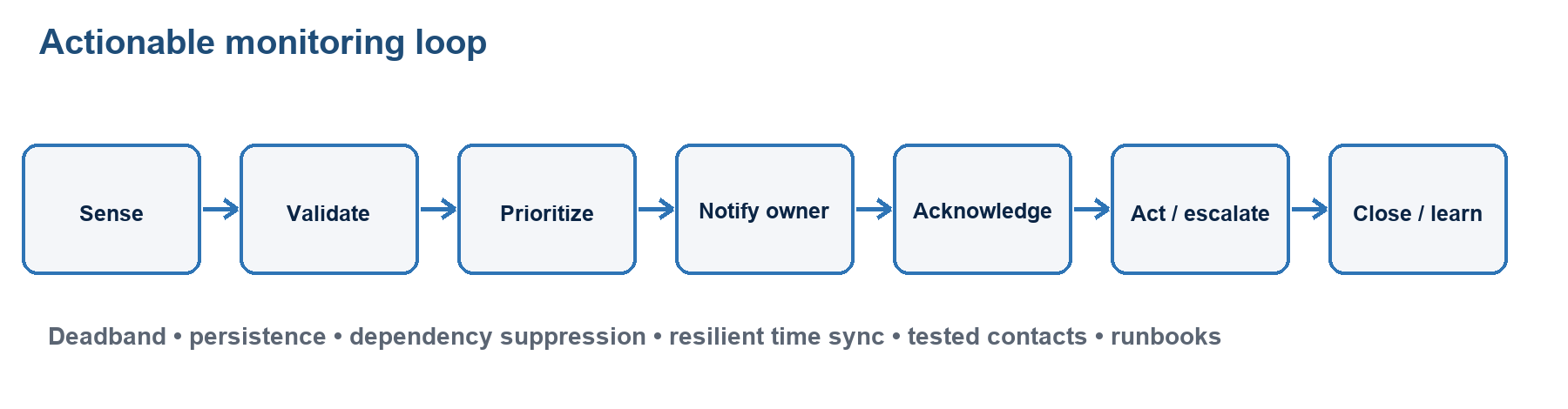
What mastery looks like
You can define monitoring outcomes, place and validate sensors, separate EMS, BMS and DCIM responsibilities, design leak detection and alarm escalation, and preserve monitoring during the failure it reports. You can turn raw telemetry into a trustworthy event with context, ownership and action; integrate open protocols securely; distinguish acknowledgment from resolution; and use analytics/AI without surrendering deterministic protection.
Core concepts
Purpose and challenge. Monitoring should detect incipient failure, protect people/equipment, confirm redundancy, guide response, prove performance/capacity, and support root-cause analysis. Challenges include multiple vendors/protocols, legacy devices, wrong sensor placement, calibration drift, noisy thresholds, missing timestamps, network/power dependence, proprietary meanings, alarm floods, stale asset models, cybersecurity, and unclear ownership. More points do not guarantee better awareness.
System boundaries.
- In R25, EMS means Environmental Monitoring System: temperature, humidity/dew point, differential pressure, water/leaks, smoke interfaces, particles or other room/rack conditions. Elsewhere EMS may mean energy management system, so define the acronym.
- BMS/BAS supervises and often controls building plant such as HVAC, pumps, valves, chillers, lighting and electrical/mechanical auxiliaries. BACnet is a vendor-independent building-automation protocol; Modbus is also common.
- DCIM means Data Centre Infrastructure Management. It combines facility/IT infrastructure views for assets, rack space, power/cooling capacity, connectivity, dependencies, trends and workflows. A DCIM model is valuable only if discovered and changed state is reconciled.
- An NMS focuses on network devices, interfaces, traffic and services, commonly using SNMP/telemetry. These platforms overlap; integration does not erase authoritative ownership or safety controls.
Monitoring architecture. Think sensor/meter → local controller or panel → gateway/protocol → supervisory platform/historian → alarm engine → notification/ticket → human/runbook. Every stage needs power, communications, time, configuration, health monitoring, security and a failure response. Critical local protections must continue safely if a dashboard or WAN fails. Avoid making the monitoring system a common control failure.
Points and placement. Monitor representative IT inlets and returns; room/row/rack pressure; utility/UPS/PDU/rack power; breaker and source state; generator/fuel; battery status; cooling-unit, pump, valve, flow, pressure and supply/return temperatures; CDU/TCS/FWS conditions; tank levels/water quality; doors/security; fire-panel status; and leaks. Choose by failure mode. A ceiling humidity sensor cannot prove the top server inlet is safe; one energy meter cannot localize an overloaded branch.
Data quality. Give each point an owner, engineering unit, range, accuracy, calibration/validation method, location, asset association, sampling interval, normal state, threshold, hysteresis/deadband, delay, priority and runbook. Detect stuck, impossible, disagreeing and stale values. Synchronize clocks. Preserve raw data and configuration changes long enough for incident analysis. Trend context together—IT load, weather, valve/fan state and temperature—to avoid false causality.
Alarm engineering. Classify by consequence and urgency, not vendor default. Use thresholds plus persistence/delay, hysteresis, rate-of-change, state and dependency logic. Correlate child symptoms under a root event; suppress only under authorized maintenance with expiry; rate-limit repeated notifications without hiding continuing risk. Route by shift and skill, provide context/action, require acknowledgment within a target, escalate on no response, and create a ticket. An alarm may clear when the measured condition returns normal; acknowledgment records receipt, reset follows system logic, and the incident is not resolved until the cause and required follow-up are complete. Test the entire chain regularly.
Water leak detection. Spot sensors detect at a point; sensing cable/rope detects along a route and can be zoned or distance-locating; flow/pressure and tank-level analytics can reveal hidden loss. Place under likely sources and paths: valves, joints, CDUs/manifolds, rear doors, CRAH/chilled-water units, drains, humidifiers, roof/risers, and low points. Provide accessible zoning, supervised circuits, compatible chemistry, labels and test ports. A rope above the actual drainage path gives false confidence. Couple alarm to an approved response/isolation sequence; automatic shutoff can itself remove cooling and needs risk analysis.
Protocols and cybersecurity. BACnet, Modbus and SNMP enable integration but do not make semantics, security or reliability automatic. Maintain a point list and mapping; use gateways deliberately; segment building/monitoring networks; least privilege; secure management versions; authenticated remote access; controlled vendor support; backups; patch/vulnerability management; logging; allowlists/firewalls; and tested restore. Default passwords and unauthenticated write access can turn visibility into a facility attack path. Where possible, a supervisory integration should read safety-critical state without overriding listed local control.
Resilience and analytics. Power critical panels, gateways, network, clocks and notification paths from appropriate resilient sources; provide local buffering and alternate out-of-band notification; alarm on loss of telemetry. Test after utility, UPS, network, controller and platform failures. Analytics and AI can find sensor drift, forecast capacity, correlate alarms and optimize cooling, but require quality data, explainable boundaries, model-drift monitoring, change approval and deterministic fallback. Never let a prediction suppress a hard life-safety or manufacturer-limit alarm.
Key distinctions
- EMS / BMS / DCIM: environmental sensing; building plant control; cross-domain infrastructure capacity/asset management.
- Monitoring / control: observe and alert versus command/set state. Integration may do both, but authority must be explicit.
- Event / alarm / incident: state change; actionable abnormal condition; managed disruption requiring coordinated response.
- Threshold / setpoint: alarm boundary versus control target.
- Acknowledged / cleared / resolved: operator received it; measured state returned; cause corrected and follow-up complete.
- Spot / cable leak sensor: point detection versus continuous route/zone detection.
- Polling / unsolicited event: supervisor requests state versus device sends change/trap; robust designs supervise both paths.
- Telemetry loss / normal value: missing data is unknown, not healthy.
- Data retention / backup: keeping history versus recoverable protected copies/configuration.
Formulas/units where relevant
- Sample count = points × samples per unit time × retention duration; use it to estimate historian scale before compression/replication.
- Availability of monitoring must include sensor, controller, gateway, network, platform, identity, notification and staff—not dashboard uptime alone.
- Hysteresis example: high alarm activates at 30°C and clears below 28°C; the 2 K deadband prevents chatter. Values are illustrative, not CDCP limits.
- Rate of change = (current value − previous value) / elapsed time; it can warn before an absolute limit.
- Alarm load per operator/shift should be measured, but no universal “acceptable number” replaces consequence-based rationalization.
Design/operations reasoning
Begin with failure modes and decisions: what can fail, how early it is detectable, who can act, and by when. Build the point list and sensor placement from that analysis. Assign one authoritative source per value while integrating views. Configure units, ranges, calibration, timestamps, thresholds, persistence, priority, dependencies, runbooks and escalation. Commission by injecting real/simulated states at the sensor, not just clicking a dashboard test. Verify local action, gateway, historian, alarm, SMS/voice/email/ticket, acknowledgment, escalation and recovery. Then trend nuisance alarms, missed incidents, stale points, response time and model accuracy; rationalize after every plant or rack change.
Common traps
- Expanding EMS as energy management when the R25 module means environmental.
- Treating BMS, DCIM and NMS as synonyms.
- Monitoring room averages instead of the threatened intake/component.
- Trusting uncalibrated, unnamed, unitless or stale points.
- Using one threshold with no hysteresis/persistence and creating alarm chatter.
- Sending every alarm to everyone, causing alert fatigue.
- Believing acknowledgment fixed the fault.
- Suppressing alarms for maintenance with no owner or automatic expiry.
- Placing leak cable where water will not travel or failing to test it wet/dry as approved.
- Automating a water shutoff without considering loss of cooling.
- Hosting monitoring on the same power/network dependency it must report, with no local buffer or alternate path.
- Giving gateways/default protocol accounts broad write access.
- Letting an AI score override local interlocks, life-safety alarms or equipment limits.
- Failing to reconcile DCIM records after moves/adds/changes.
8 closed-book retrieval prompts with concise answers
- Prompt: What does EMS mean in CDCP R25?
Answer: Environmental Monitoring System; define it because EMS can mean energy management elsewhere.
- Prompt: Separate EMS, BMS and DCIM in one line.
Answer: EMS senses environment; BMS supervises/controls building plant; DCIM models/manages data-centre assets, capacity and dependencies across IT/facilities.
- Prompt: What is the monitoring chain?
Answer: Sensor/meter → controller/panel → gateway/protocol → platform/historian → alarm/notification/ticket → human runbook.
- Prompt: Why is missing telemetry not a normal reading?
Answer: It is unknown state and may be the first sign of sensor, controller, network, power or platform failure.
- Prompt: What prevents threshold chatter?
Answer: Suitable hysteresis/deadband, persistence/delay and state logic.
- Prompt: Contrast spot and cable leak detection.
Answer: Spot sensors cover a point; sensing cable covers a route/zone and may locate distance.
- Prompt: What is the difference between acknowledged and resolved?
Answer: Acknowledged means receipt; resolved means cause corrected, service/state verified and follow-up recorded.
- Prompt: What makes monitoring resilient?
Answer: Resilient local sensors/controllers, power, network/time, buffering, platform and alternate notification, plus telemetry-loss alarms and tested procedures.
Authoritative source URLs
- EPI, current CDCP syllabus and exam overview: epi-training.com source
- HPE, CDCP R25-aligned course outline (modules 8–14): hpe.com source
- TIA, ANSI/TIA-942-C overview (May 2024): tiaonline.org source
- TIA, TIA-568 commercial cabling family: tiaonline.org source
- IEC, IEC 60297-3-100:2008 basic dimensions for the 482.6 mm rack/cabinet family: webstore.iec.ch source
- ASHRAE, data centres and liquid-cooling fundamentals: handbook.ashrae.org source
- U.S. DOE FEMP, 2024 energy-efficient data-centre design guide: energy.gov source
- U.S. DOE FEMP, cooling-water efficiency and WUE: energy.gov source
- U.S. DOE, seasonal/underground thermal energy storage: energy.gov source
- ISO, ISO/IEC 30134-9:2022 Water Usage Effectiveness: iso.org source
- Open Compute Project, Advanced Cooling Solutions: opencompute.org source
- NFPA, NFPA 75 fire protection of information technology equipment: link.nfpa.org source
- NFPA, NFPA 2001:2025 clean-agent extinguishing systems: link.nfpa.org source
- OSHA, emergency action plans and portable extinguishers: osha.gov source and osha.gov source
- NIST SP 800-53 Rev. 5, Physical and Environmental Protection controls: csrc.nist.gov source
- ASHRAE Standard 135 BACnet resources: data.ashrae.org source
- IETF SNMP architecture and management information: rfc-editor.org source and rfc-editor.org source
Supplemental Operations and Management Layer
Scope and exam-status warning
Operations and Management is not a separately listed module in the public CDCP R25 syllabus brochure. The public R25 topic list is organized primarily around facilities: the mission-critical site, standards, building and construction, raised floors, lighting, power, electromagnetic fields, racks, cooling, water, network infrastructure, fire protection, physical security and safety, and auxiliary systems. Nevertheless, the current EXIN certification page still identifies Facilities, Operations and Management as the main subjects of CDCP, while an older public EPI/EXIN examination-preparation guide allocated six of forty questions to operations. Consequently, the authorized R25 course manual, accredited trainer guidance, and current exam specifications control wherever they differ from this supplemental chapter or the older blueprint.
This chapter is therefore a protection layer, not an assertion of an additional R25 module or a current question weighting. It connects the technical facility to the people, agreements, procedures, records, and decisions that keep it available. Use it after mastering the explicit R25 facility modules, and reconcile its terminology with the authorized R25 material.
Primary status sources:
- EPI/TÜV NORD CDCP R25 brochure
- Current EXIN CDCP certification page
- Older public EPI/EXIN CDCP preparation guide (2017; not an R25 specification)
Why operations is cross-module
A well-designed facility can still fail because a technician works on the wrong breaker, an obsolete single-line diagram is used, a vendor enters without the required supervision, a critical alarm has no owner, or two teams each assume that the other will act. Operations converts physical capability into dependable service. It does this by defining what service is promised, who may act, which evidence is required, how work is controlled, how abnormal conditions are escalated, and how lessons are fed back into design and procedure.
The learner should be able to connect every facility module to an operating control. Examples include load and phase records for power, rack-intake trends for cooling, impairment permits for fire protection, controlled access for security, cable records for networks, calibration for sensors, and water-autonomy tests for cooling or fire supplies. The common objective is controlled, repeatable work with clear accountability.
1. Service portfolio, service catalogue, and service-level controls
A service portfolio is the broad management view of services across their lifecycle. It can include proposed, live, changing, and retired services. It answers questions such as what the organization offers, why it exists, who funds or consumes it, what assets support it, and whether it should continue.
A service catalogue is the usable view of live or available services and their agreed characteristics. For a data centre, entries might include colocation space, rack power, cross-connects, remote hands, environmental conditions, access arrangements, backup services, and reporting. The catalogue should state eligibility, request method, standard options, dependencies, support hours, and service targets without promising capabilities the underlying facility cannot deliver.
Three agreements are easily confused:
- A service-level agreement (SLA) is between a service provider and its customer. It expresses measurable commitments such as availability, response, restoration, reporting, or service hours.
- An operational-level agreement (OLA) is an internal agreement between teams that collectively support an SLA. For example, facilities, network, service desk, and security teams may have internal response and handoff obligations.
- An underpinning contract is an agreement with an external supplier whose performance supports the service. Examples include generator maintenance, fuel replenishment, carrier service, UPS support, fire-system maintenance, or security guarding.
The SLA should be traceable to operational capability. If a customer target depends on a four-hour generator response but the maintenance contract provides next-business-day attendance, the promise is unsupported. Likewise, an SLA availability percentage should define the service, measurement point, calculation period, exclusions, maintenance treatment, and evidence source. Service-level management is not merely writing the agreement; it is the cycle of defining, agreeing, monitoring, reporting, reviewing, and improving it.
Common confusion: a supplier contract does not transfer the operator's accountability for safe access, change control, validation, recordkeeping, and customer communication.
2. Roles, RACI, escalation, and shift handover
Every recurring activity and foreseeable emergency needs an owner. Job titles alone are insufficient because several teams may touch one event. A RACI matrix clarifies participation:
- Responsible: performs the work.
- Accountable: owns the result and approves or answers for it. Normally there should be one clearly accountable role for a given outcome.
- Consulted: provides input before or during the decision.
- Informed: receives the decision or status.
RACI complements, rather than replaces, procedures and competent judgment. An emergency operating procedure still needs explicit authority: who may declare an incident, transfer load, invoke an EOP, isolate equipment, contact emergency services, notify customers, or approve re-entry. Escalation should specify triggers, levels, response times, alternates, and what happens when the primary contact does not acknowledge.
Do not confuse RACI with a security access matrix. RACI assigns participation and accountability for work; an access matrix maps named roles or identities to permitted zones, times and conditions. A person may be responsible for a task yet still require separate authorization, escort or temporary access.
Shift handover is a risk-control activity. A useful handover records at least:
- Current alarms, incidents, impairments, bypasses, overrides, inhibited detections, and temporary configurations.
- Equipment out of service and the resulting redundancy state.
- Open permits, active changes, vendor presence, and work boundaries.
- Capacity concerns, abnormal trends, outstanding inspections, and required readings.
- Customer-impacting conditions, notifications already made, and next escalation times.
- Exact ownership of each unfinished action.
The receiving operator should acknowledge the handover and challenge unclear conditions. Verbal transfer alone is fragile; a controlled log provides continuity and audit evidence. High-risk work spanning a shift should have a deliberate face-to-face or live handoff, not simply an unread ticket.
Common confusion: “Responsible” and “accountable” are not synonyms. The technician may execute a MOP while the change owner remains accountable for its outcome.
3. Competency, training, and authorization
Attendance at training is not the same as competence. A defensible competency system begins with a skills matrix that maps each role to required knowledge, practical skills, safety qualifications, site authorization, and refresher interval. Typical layers are:
- Site induction and general safety.
- Role-specific technical instruction.
- Supervised practice or observation.
- Assessment through questioning, demonstration, drill, or simulation.
- Formal authorization for defined equipment or activities.
- Periodic refresher training and reassessment after change, incident, or extended absence.
Training records should identify the learner, content/version, instructor or assessor, date, result, limitations, authorization, and expiry or review date. Emergency drills should cover realistic communications and decision-making, not only equipment manipulation. Drills need clear safety boundaries so they do not create the outage they are intended to prevent.
Contractors also require verification. A vendor's corporate certification does not establish knowledge of the site's A/B topology, local isolation points, emergency routes, access rules, or current impairment state. Site-specific induction and task authorization remain necessary.
Common confusion: experience can support competence, but undocumented experience does not replace current authorization for hazardous or site-specific work.
4. Maintenance strategy and maintenance agreements
Maintenance preserves required function and exposes latent defects before they coincide with another failure. Do not force every label into one mutually exclusive list; use two axes and learn the authorized course terminology:
- Maintenance trigger/mechanism: predetermined preventive maintenance is scheduled by time, usage, starts or cycles; condition-based preventive maintenance is initiated from observed condition; predictive maintenance is a condition-based approach that uses analysis or prognosis to forecast degradation; corrective maintenance acts after a fault or defect is found.
- Planning/urgency: work may be planned/scheduled or urgent/emergency. “Emergency” describes urgency, not a separate technical failure mechanism, and it still requires the safest achievable controls and complete records.
Condition evidence can include vibration, thermography, oil analysis, battery impedance, breaker timing or deteriorating efficiency. Terminology differs across standards and organizations, so define the trigger rather than relying on a label alone.
A maintenance agreement should define assets and serials, task scope, maintenance standard, frequency, service window, staffing/competency, parts and consumables, response and restoration targets, remote support, escalation, safety responsibilities, site access, reporting, test evidence, exclusions, and warranty implications. It should also state how urgent attendance works outside normal hours and how performance is reviewed.
Before maintenance, operators should verify the actual—not assumed—system state. Questions include whether redundant capacity is healthy, whether another impairment exists, whether current load can be carried after isolation, whether bypass paths have capacity, and whether dependencies such as cooling or controls will remain available. Planned work normally needs an approved MOP, risk assessment, communication plan, rollback criteria, and post-work functional checks.
After maintenance, the team should remove temporary grounds, jumpers, overrides, inhibits, tools, and barriers; restore the approved configuration; verify alarms and monitoring; record measurements; update asset history; and confirm the redundancy state. “Vendor completed” is not sufficient closure evidence.
Safety remains controlling. Electrical isolation and hazardous-energy control should follow applicable law and site procedures. In the United States, OSHA's general control-of-hazardous-energy rule, 29 CFR 1910.147, excludes electrical-utilization hazards covered by Subpart S; 29 CFR 1910.333 addresses selection and use of electrical work practices. Local jurisdictional requirements govern the actual site.
5. Floor, asset, and capacity management
Floor management is the controlled placement and lifecycle of equipment within the technical space. It integrates:
- Rack position, dimensions, weight, anchoring, and access clearances.
- Static, concentrated, and rolling floor loads.
- A and B power availability, plug/receptacle type, branch capacity, phase balance, and fault-protection limits.
- Cooling capacity, airflow direction, containment, intake conditions, and high-density exceptions.
- Copper/fiber pathways, port capacity, diversity, bend radius, and labeling.
- Fire detection/suppression coverage, egress, and security zones.
- Asset ownership, serial/configuration data, support status, and decommissioning.
Capacity is multi-dimensional. Empty rack units do not prove usable capacity if power, cooling, weight, network ports, or upstream redundancy is exhausted. Capacity records should distinguish installed, usable, reserved, allocated, and consumed capacity and should include thresholds and forecasts. A growth plan should account for lead times: switchgear, transformers, generators, chillers, and utility upgrades cannot be added as quickly as servers.
An install/move/add/change process should validate the proposed equipment against every constraint before approval. After installation, actual readings and asset records should be reconciled with the plan. Decommissioning should remove abandoned cables, labels, reservations, credentials, monitoring points, and combustible packaging while preserving required audit evidence.
Useful management-system anchors are ISO 55001:2024 for asset management and ISO/IEC 20000-1 for service management.
6. SOP, MOP, EOP, and document control
Operational documents should use consistent terminology. The labels below are common data-centre conventions; the site document hierarchy and authorized R25 material control exact terminology:
- An SOP (standard operating procedure) describes a routine, repeatable operating activity under normal conditions, such as a scheduled inspection or standard start/stop sequence.
- A MOP (method of procedure) is the detailed, approved execution plan for a specific planned intervention or change. It commonly includes prerequisites, system state, roles, communication, step sequence, hold points, expected indications, abort criteria, rollback, and post-work verification.
- An EOP (emergency operating procedure) directs rapid, safe response to an abnormal or emergency condition. It should prioritize life safety, stabilization, escalation, service protection, and recovery, with concise decision points suitable for stressful use.
A MOP is not safe merely because it is detailed. It must reflect the current as-built system, present load, active impairments, trained personnel, and reviewed risk. Steps should identify the exact equipment, expected result, and stop condition; vague instructions such as “switch to backup” invite error. Independent verification or peer checks are appropriate for high-consequence actions.
Document control should give each controlled item an identifier, title, owner, version, approval, effective date, review date, change history, access classification, and archive status. Operators need one authoritative current copy. Superseded copies should be withdrawn from points of use while retained according to records policy. Single-line diagrams, sequences of operation, alarm matrices, rack elevations, cable records, and equipment settings require the same discipline as prose procedures.
A backup only proves that a file can potentially be recovered. It does not prove that the file is accurate, approved, current, readable, or available during a network outage. Critical procedures should remain accessible under the failure conditions in which they are needed.
7. Change management
Change management controls risk without preventing necessary improvement. A proportionate workflow includes:
- Describe the purpose, scope, assets, and intended result.
- Identify service, safety, security, capacity, compliance, and shared-dependency impacts.
- Check present load, alarms, impairments, conflicting work, and freeze periods.
- Classify risk and obtain appropriate technical, operational, customer, and safety approval.
- Develop and peer-review the MOP, test plan, communication plan, rollback, and abort criteria.
- Confirm staff, vendor, tools, spares, access, and monitoring readiness.
- Conduct a pre-job briefing and establish control of the work area.
- Execute one controlled step at a time, recording actual results and stopping on unexpected conditions.
- Validate service, redundancy, alarms, settings, and documentation.
- Close the change and conduct a post-implementation review when results, risk, or learning warrant it.
Standard changes may be pre-authorized only when genuinely repeatable, low risk, and performed within a proven model. Emergency changes use expedited approval because delay creates greater risk; they are not exempt from documentation, validation, or retrospective review.
Common confusion: a successful technical action can still be a failed change if it creates undocumented configuration drift, hidden loss of redundancy, or an uncommunicated customer impact.
8. Vendor management
Vendors often hold specialized knowledge, but their work crosses facility, security, safety, and service boundaries. Control the full lifecycle:
- Due diligence: competence, authorization, insurance, safety record, technical capability, financial/parts support, and subcontractor controls.
- Contracting: scope, service levels, escalation, reporting, confidentiality, data handling, parts, exclusions, and exit provisions.
- Onboarding: site rules, hazards, emergency routes, topology relevant to the task, access zones, photography/removable-media restrictions, and incident reporting.
- Work control: named personnel, identity verification, approval, escort where required, permits, MOP/EOP role, tool/material control, and start/stop communication.
- Performance: response, restoration, maintenance quality, repeat defects, reports, parts availability, safety observations, and corrective actions.
- Offboarding: revoke badges/accounts/remote access, recover keys and information, close permits, return records, and preserve support history.
The operator should verify vendor statements against site evidence. A manufacturer procedure can be technically correct yet unsafe in the facility's current configuration. Conversely, a site procedure must respect manufacturer limits and warranty requirements.
9. Alarm ownership and operational response
Monitoring creates value only when an abnormal condition leads to timely, correct action. Every alarm should have a defined source, meaning, priority, owner, notification route, response target, runbook, escalation path, reset/closure rule, and record-retention requirement.
The operational lifecycle is:
detect → validate → prioritize → notify → acknowledge → diagnose → act/escalate → restore or contain → verify → close → review
Thresholds should reflect equipment limits and service risk, with sensible warning/critical levels, delays, deadbands, rate-of-change rules, and dependencies. Excessive nuisance alarms cause alarm fatigue; aggressive suppression can hide a precursor. Maintenance suppression should be approved, time-bound, visible at handover, and removed after testing.
Acknowledgement means someone has accepted ownership; it does not mean resolution. If the primary recipient does not acknowledge in time, notification should escalate through alternate people and channels. Time synchronization is essential for reconstructing events across UPS, switchgear, BMS, DCIM, fire, access, and network systems.
A critical alarm review should ask whether the sensing was valid, the priority correct, the notification received, the runbook usable, the response timely, dependencies understood, and corrective actions completed. EPI's public Data Centre Operations Standard is a useful supplemental framework for operational governance.
10. Five end-to-end failure questions
For every technical system, trace these five questions from the customer service through the facility, people, process, and suppliers:
- What is the normal operating path? Identify sources, conversion stages, distribution, controls, monitoring, responsible teams, and external dependencies.
- What happens when each component or dependency fails? Include protective action, transfer behavior, alarm, remaining capacity, service consequence, and common-mode failure.
- How can each element be maintained without unacceptable service interruption or safety risk? Check isolation, alternate path, load, permits, MOP, competency, rollback, and concurrent work.
- What shared dependency defeats the apparent redundancy? Look for common switchgear, controls, fuel, water, chilled-water loops, carrier ducts, fire zones, access routes, vendors, documentation, and operator error.
- What evidence proves the system is healthy and restored? Require readings, functional tests, alarm verification, trend/baseline comparison, current drawings, asset history, shift-log entry, and explicit confirmation of the redundancy state.
These questions make Operations and Management cross-module. They turn a diagram showing two components into a defensible claim about service capability.
Retrieval practice: 15 original prompts with concise answers
These are study prompts, not actual or reconstructed examination questions.
- Prompt: The customer-facing agreement promises a two-hour restoration target, but the external generator-maintenance supplier promises attendance within four hours. Name both agreement types and the control gap.
Answer: The customer agreement is an SLA; the supplier agreement is an underpinning contract. The supplier commitment cannot support the customer target without another response or restoration control. Source: ISO/IEC 20000-1 service management; current EXIN CDCP page.
- Prompt: What is the practical distinction between a service portfolio and a service catalogue?
Answer: The portfolio manages services across their lifecycle, including proposed and retired services; the catalogue presents live or available services and how they are obtained and supported. Source: ISO/IEC 20000-1.
- Prompt: In RACI, who owns the outcome when a technician performs an approved switching procedure?
Answer: The technician can be Responsible, while the designated change or system owner remains Accountable for the outcome. Source: EPI Data Centre Operations Standard.
- Prompt: Name four conditions that must be included in a high-risk shift handover.
Answer: Any four of active alarms/incidents, equipment out of service, lost redundancy, bypasses/overrides/inhibits, open permits/changes, vendors onsite, abnormal trends, customer notifications, and named ownership of next actions. Source: ISO/IEC TS 22237-7:2018 data-centre operations; EPI DCOS.
- Prompt: Why does a course-attendance record not by itself establish operator competence?
Answer: Competence requires demonstrated knowledge and skill plus authorization for the role/site; attendance records only participation. Assessment, supervised practice, authorization, and refresher control complete the evidence. Source: ISO/IEC TS 22237-7:2018.
- Prompt: Thermography shows a termination becoming hotter over successive inspections. Which maintenance type is indicated?
Answer: Condition-based preventive maintenance; predictive maintenance is the more specific label when analysis/prognosis forecasts the developing failure. The key is that measured deterioration, rather than elapsed time alone, triggers the intervention. Source: IEC Electropedia maintenance terminology; reconcile the label with the authorized R25 course material.
- Prompt: What must be checked before taking one UPS module out of service in an N+1 arrangement?
Answer: Actual load, health and capacity of remaining modules, bypass/distribution condition, concurrent impairments/work, cooling and controls, the approved MOP, rollback criteria, and expected alarms. Source: EPI/TÜV NORD R25 brochure; IEC 62040-3 UPS reference.
- Prompt: Why do ten empty rack units not prove that a new server can be installed?
Answer: Usable capacity also depends on rack and floor load, A/B power, branch and upstream capacity, cooling/airflow, network ports/pathways, clearances, fire coverage, and redundancy limits. Source: ISO 55001:2024; ANSI/TIA-942-C.
- Prompt: Which document is most appropriate for a planned breaker replacement, and what two controls distinguish it from a routine SOP?
Answer: A MOP; it is specific to the planned intervention and includes explicit abort/rollback criteria and post-work validation, normally with change approval and present-state checks. Source: EPI DCOS; ISO/IEC TS 22237-7:2018.
- Prompt: Why is keeping a backup of a single-line diagram insufficient document control?
Answer: Recoverability does not prove accuracy, approval, current version, availability at the point of use, or alignment with the as-built system. Source: ISO/IEC TS 22237-7:2018; ISO 55001:2024.
- Prompt: An emergency change restores service but leaves an undocumented temporary bypass. Is the change complete?
Answer: No. Emergency timing can expedite approval, but closure still requires configuration restoration or explicit risk acceptance, validation, documentation, communication, and retrospective review. Source: ISO/IEC 20000-1; EPI DCOS.
- Prompt: A manufacturer-certified technician arrives for maintenance. What site controls still apply?
Answer: Identity and authorization checks, site induction, access/escort rules, safety permits, approved work scope/MOP, awareness of current impairments, start/stop communication, supervision as required, and closure evidence. Source: NIST SP 800-53 physical protection controls; OSHA lockout/tagout.
- Prompt: A critical high-temperature alarm was sent but no one acted. Which control is missing if the notification platform worked correctly?
Answer: Effective ownership and acknowledgement/escalation control. Sending a message is not the same as assigning and confirming response responsibility. Source: EPI DCOS; ISO/IEC TS 22237-7:2018.
- Prompt: What is the first end-to-end question to ask when validating a dual-path power or network design?
Answer: “What is the normal operating path?” Trace both paths through every source, conversion/distribution stage, control, monitor, team, and supplier before evaluating failures. Source: ANSI/TIA-942-C; EPI/TÜV NORD R25 brochure.
- Prompt: What evidence should close a maintenance task after equipment appears to be running normally?
Answer: Functional and alarm tests, expected readings, removal of temporary controls/tools, approved configuration restoration, updated records/drawings where required, asset history, handover entry, and explicit verification of redundancy. Source: ISO 55001:2024; EPI DCOS.
Final mastery check
The operations layer is mastered when the learner can take any R25 facility topic—power, cooling, fire, network, physical security, water, or monitoring—and explain not only how it is designed, but also who owns it, what service it supports, how it is monitored, how it can be safely maintained, what document governs the work, how a vendor is controlled, how an alarm escalates, what shared dependency can defeat it, and what evidence proves restoration.
Practice examination A
Use this only after first-pass coverage of every module. Set a 60-minute timer, close every source, remove your phone and answer all 40 questions in one sitting. Record K, U or G beside each answer. The questions are independent practice items written for this guide; they are not official EPI/EXIN questions and do not predict the live exam distribution.
Questions
Q01 — A service is available for 99.95% of a non-leap year. Approximately how much total downtime does that allow?
- A. 26 minutes
- B. 4 hours 23 minutes
- C. 8 hours 46 minutes
- D. 43 hours 48 minutes
Q02 — Two complete power paths enter a data hall, but both depend on one fuel pump controller during an extended utility failure. What is the principal design concern?
- A. Harmonic distortion
- B. A common-mode single point of failure
- C. Excessive apparent power
- D. Insufficient rack-unit capacity
Q03 — A voluntary data-centre standard conflicts with a legally adopted local fire code. Which source normally controls the fire design?
- A. The voluntary standard because it is data-centre-specific
- B. The equipment vendor's installation manual only
- C. The adopted code and direction of the authority having jurisdiction
- D. Whichever source permits the least expensive design
Q04 — Which statement best distinguishes a standard from a guideline?
- A. A standard can state defined requirements and may become binding through law or contract; a guideline primarily recommends practice
- B. A guideline is always legally enforceable; a standard never is
- C. Standards apply only internationally; guidelines apply only nationally
- D. There is no practical difference
Q05 — Which candidate site most clearly introduces a hidden continuity risk despite excellent utility capacity?
- A. A site with two substations whose feeders share one flood-prone utility tunnel
- B. A site with expansion land and two verified carrier entrances
- C. A site with a maintained secure loading area
- D. A site whose ambient climate permits more economizer hours
Q06 — Which supporting-space decision most directly reduces contamination and security risk in the white space?
- A. Route all deliveries through the data hall
- B. Provide separate receiving, staging and unpacking space before equipment enters the data hall
- C. Store cardboard beside the racks for reuse
- D. Put the loading dock inside the main distribution area
Q07 — A heavy cabinet is moved across a raised floor. Which load rating is most directly relevant during the move?
- A. Luminous flux
- B. Rolling load
- C. Power factor
- D. Relative humidity
Q08 — Underfloor cables block airflow and unsealed cut-outs leak supply air. What is the best first correction?
- A. Lower every room temperature set point
- B. Restore plenum airflow management by removing obstruction and sealing uncontrolled openings
- C. Remove rack blanking panels
- D. Increase humidity to its highest allowable value
Q09 — A work plane receives 24,000 lumens uniformly over 300 m². What is the idealized average illuminance?
- A. 8 lux
- B. 80 lux
- C. 720 lux
- D. 7,200 lux
Q10 — A cooling plant requires three identical operating pumps to support the design load and has four installed. What is the component-level redundancy description?
- A. N
- B. N+1
- C. 2N
- D. 2(N+1)
Q11 — Which statement about 2N is most accurate?
- A. It always proves that every maintenance activity can be performed without service risk
- B. It means two complete capacity systems or paths, but common dependencies and operating procedures still have to be examined
- C. It is identical to N+1 in every respect
- D. It eliminates the need for testing and monitoring
Q12 — Which application most strongly suggests an STS rather than an ATS?
- A. Transferring a facility bus between utility and a generator that is still starting
- B. Very fast transfer of a critical single-input AC load between two compatible live sources
- C. Converting AC to DC for a battery
- D. Correcting fibre polarity
Q13 — Ignoring efficiency losses, what is the approximate real power of a balanced 400 V three-phase load drawing 50 A at power factor 0.8?
- A. 16 kW
- B. 27.7 kW
- C. 40 kW
- D. 55.4 kW
Q14 — A load remains at 80 kW while its power factor falls from 1.0 to 0.8. What happens to required apparent power?
- A. It falls from 80 kVA to 64 kVA
- B. It remains 80 kVA
- C. It rises from 80 kVA to 100 kVA
- D. It becomes 160 kWh
Q15 — Which UPS topology normally conditions the load continuously by rectifying input AC to DC and then inverting DC to AC?
- A. Online double-conversion
- B. Standby/offline only
- C. Passive transfer switch
- D. Isolation monitor
Q16 — Which battery-control package is most important for a large lithium-ion installation?
- A. Ignore cell temperature because voltage alone is sufficient
- B. Cell-level monitoring, a suitable battery management system, thermal-event detection/mitigation and an approved emergency response design
- C. Place all cells beside a heat source to equalize temperature
- D. Disable protective trips to prevent nuisance alarms
Q17 — Which disturbance is most directly associated with nonlinear loads drawing a distorted current waveform?
- A. Harmonics
- B. Luminous intensity
- C. Rolling floor load
- D. Optical return loss
Q18 — What is the safest and most useful interpretation of a thermographic hot spot?
- A. It proves the exact failure mechanism by itself
- B. It is a condition indicator to investigate under known load and emissivity conditions, using qualified electrical-safety procedures
- C. It should be touched immediately to confirm temperature
- D. It can be ignored if the equipment is redundant
Q19 — A low-frequency magnetic field near sensitive equipment is traced to separated phase and return conductors carrying high current. Which correction is most fundamental?
- A. Increase the loop area
- B. Route associated conductors together to reduce loop area, then verify by measurement
- C. Add cardboard around the cable
- D. Increase lighting level
Q20 — Which rack practice most directly prevents hot exhaust from short-circuiting into server inlets?
- A. Leave unused rack spaces open
- B. Install blanking panels and preserve front-to-rear airflow separation
- C. Put both rack PDUs across the front intake
- D. Coil excess cable in front of the fans
Q21 — A dual-corded server is connected to rack PDU A with both cords. What is the main defect?
- A. It consumes no real power
- B. The two cords do not provide path diversity because both depend on source A
- C. It necessarily causes a ground fault
- D. It converts the server into a single-phase generator
Q22 — Which statement correctly distinguishes bypass airflow from recirculation?
- A. Bypass air returns without absorbing IT heat; recirculated air is hot exhaust that reaches IT inlets again
- B. They are two names for the same humidity condition
- C. Bypass occurs only in liquid systems; recirculation occurs only outdoors
- D. Recirculation always improves efficiency
Q23 — Why is dew point often more useful than relative humidity alone when assessing moisture risk?
- A. Dew point directly indicates air pressure
- B. Dew point describes absolute moisture content more consistently as dry-bulb temperature changes
- C. Dew point measures luminous flux
- D. Relative humidity never changes
Q24 — What is the defining high-level distinction between a CRAC and a CRAH?
- A. A CRAC is always outdoors and a CRAH is always under a floor
- B. A CRAC typically uses direct-expansion refrigeration at the unit; a CRAH uses chilled water supplied to a coil
- C. A CRAH cannot use fans
- D. A CRAC contains no heat exchanger
Q25 — What is the main thermodynamic purpose of hot- or cold-aisle containment?
- A. Mix supply and return air as early as possible
- B. Reduce mixing between supply air and hot exhaust so cooling capacity is used more effectively
- C. Eliminate the need for rack airflow management
- D. Raise cable insertion loss
Q26 — In a direct-to-chip liquid-cooling design, what is a common function of a coolant distribution unit (CDU)?
- A. Translate an access badge into a CCTV image
- B. Control the technology coolant loop and transfer heat to the facility loop while keeping the loops appropriately separated
- C. Convert lux to lumens
- D. Replace all fire detection
Q27 — What is the central idea of Seasonal Thermal Energy Storage (STER) in the cooling context?
- A. Store thermal energy or a cold resource across seasons and use it when cooling demand or conditions make it valuable
- B. Store network packets in winter
- C. Operate batteries only in summer
- D. Increase hot-air recirculation
Q28 — What should primarily determine backup-water capacity for a water-dependent cooling system?
- A. The colour of the pipe
- B. Required operating duration, consumption rate, replenishment time, concurrent demands and business risk
- C. Rack-unit count alone
- D. The number of CCTV cameras
Q29 — In the TIA-942 structured cabling hierarchy, which space is the central distribution point that commonly connects the entrance facilities and horizontal distribution areas?
- A. EDA
- B. ZDA
- C. MDA
- D. Work area outlet in an office
Q30 — What is the primary purpose of an optional ZDA?
- A. Provide a consolidation/interconnection point between horizontal distribution and equipment distribution areas to support flexible changes
- B. Store diesel fuel
- C. Suppress a fire with inert gas
- D. Convert three-phase power to light
Q31 — Two carriers enter through different doors but share the only manhole outside the property. What should the resilience review conclude?
- A. Complete diversity is proven by different door labels
- B. The shared manhole is a common-route dependency that can defeat simultaneous availability
- C. Carrier diversity is unrelated to physical pathways
- D. Add a third patch panel in the same manhole
Q32 — Which result belongs most clearly to balanced copper-link certification rather than fibre certification?
- A. Near-end crosstalk
- B. Optical time-domain reflectometer event trace
- C. Fibre connector end-face inspection
- D. Optical polarity
Q33 — Which detection approach is commonly chosen to identify very small smoke concentrations at an early stage?
- A. Aspirating smoke detection
- B. A water flow switch only
- C. A handheld extinguisher
- D. A rack door lock
Q34 — Which statement best describes a typical single-interlock pre-action sprinkler concept?
- A. The pipe is always open at every nozzle
- B. A separate detection event trips the pre-action valve to admit water to normally dry piping; water discharges only from a sprinkler that opens
- C. It cannot use water
- D. It requires no detection or supervision
Q35 — Why is an enclosure integrity test important for a gaseous total-flooding system?
- A. It verifies that the room can maintain the required agent concentration for the design hold time
- B. It measures copper crosstalk
- C. It sizes the generator fuel tank
- D. It replaces occupant alarms
Q36 — Why must fire-class answers be tied to the applicable jurisdiction and course material?
- A. Fire classes and extinguisher labels can differ between classification systems, especially for energized electrical and cooking-oil hazards
- B. Fire has no common scientific basis
- C. Every country prohibits extinguishers
- D. Class labels are set by equipment rack height
Q37 — Which control most directly reduces tailgating into a high-security data hall?
- A. An interlocked portal/mantrap with individual authentication and anti-tailgating detection, supported by procedure
- B. A public sign-in sheet outside the property
- C. One shared badge for the whole shift
- D. Propping the door open during deliveries
Q38 — Before servicing equipment with electrical, mechanical and stored-energy hazards, which sequence principle is essential?
- A. Press the stop button and assume all energy is isolated
- B. Identify every source, shut down and isolate, apply lockout/tagout as required, block or dissipate stored energy, and verify de-energization/isolation with the applicable test method
- C. Remove protective guards while it operates
- D. Depend only on a remote alarm
Q39 — Which statement best distinguishes EMS, BMS and DCIM?
- A. They are exact synonyms
- B. EMS focuses on environmental sensing, BMS on building-system monitoring/control, and DCIM on integrated data-centre capacity/energy/asset and facility information, with product overlap
- C. EMS supplies utility power, BMS is a battery type, and DCIM is a fire agent
- D. Only DCIM can display a temperature
Q40 — Which alarm design best limits alarm fatigue without concealing genuine risk?
- A. Send every raw sensor change at the same severity to every employee
- B. Use owned severities, persistence/deadband logic, dependency suppression, actionable messages, acknowledgement/escalation and periodic test/review
- C. Disable alarms after the first nuisance event
- D. Notify only after customers report an outage
Answer key and rationales
Q01 — B. Annual minutes are 365 × 24 × 60 = 525,600. Unavailability is 0.05% = 0.0005; 525,600 × 0.0005 = 262.8 minutes, or about 4 hours 23 minutes. C corresponds to 99.9%; A is roughly 99.995%; D is ten times too large.
Q02 — B. Nominally separate paths can still fail together through a shared dependency. The fuel-pump controller is a common-mode single point during the stated scenario. Harmonics and apparent power are electrical-quality/sizing concepts, and rack units measure equipment height.
Q03 — C. Applicable law, adopted codes and the AHJ control legal compliance. A voluntary standard may be excellent practice or contractually binding, but it does not override a controlling code. Cost never determines authority.
Q04 — A. Standards contain agreed specifications or requirements and become binding when adopted or contracted; guidelines normally recommend. International/national scope does not define the distinction, and the terms are not interchangeable.
Q05 — A. The two sources share a flood-prone route, so the apparent diversity can fail in one event. The other choices generally support resilience or efficiency, though every site still needs full risk assessment.
Q06 — B. Receiving/staging/unpacking keeps unauthorized delivery activity, cardboard, dust and packaging away from the controlled white space. Routing deliveries or storing combustibles in the hall increases risk; an MDA is a cabling function, not a loading dock.
Q07 — B. Rolling-load capability addresses moving equipment and transition stresses. Uniform and concentrated ratings still matter in the final placement, but are not the most direct answer to “during the move.”
Q08 — B. Restore the intended plenum first: remove blockages and seal unmanaged leakage with appropriate grommets/firestopping. Lowering set points wastes energy and may not deliver air to the inlets; removing blanking panels worsens recirculation.
Q09 — B. Lux equals lumens per square metre: 24,000/300 = 80 lux under the idealized assumptions. The question deliberately excludes utilisation and maintenance factors.
Q10 — B. Three operating units are N; the fourth identical unit is one additional module, so the arrangement is N+1 at that defined level. This alone says nothing about distribution paths or other dependencies.
Q11 — B. 2N describes two complete capacity systems/paths at a defined boundary. It does not by itself prove concurrent maintainability, fault tolerance, proper isolation or absence of common-mode dependencies. Testing and monitoring remain essential.
Q12 — B. An STS uses solid-state devices for very fast transfer of a load between compatible live AC sources. An ATS commonly transfers a larger bus between utility/generator-type sources and cannot transfer to a generator before it is ready. Neither device is a rectifier or cabling tester.
Q13 — B. Three-phase real power is √3 × Vline × Iline × PF. 1.732 × 400 × 50 × 0.8 ≈ 27,712 W = 27.7 kW. Apparent power before applying PF is about 34.6 kVA, which is not listed; D doubles the correct real-power result.
Q14 — C. kVA = kW/PF, so 80/0.8 = 100 kVA. kWh is energy, not apparent power. Lower power factor requires more current/apparent capacity for the same useful kW.
Q15 — A. Online double-conversion normally maintains the AC–DC–AC path while the inverter feeds the protected load, subject to operating modes and bypass. A standby UPS normally transfers after a disturbance and does not condition continuously through the full conversion path.
Q16 — B. Lithium-ion risk control is system-level: suitable chemistry and enclosure, cell monitoring and a battery management system (battery BMS), protection, thermal detection/mitigation, fire strategy and emergency procedure. Removing trips or adding heat defeats safety.
Q17 — A. Nonlinear electronic loads can draw nonsinusoidal current and create harmonic distortion, affecting conductors, transformers and protection. The other options come from lighting, structure and fibre testing.
Q18 — B. Thermal imaging reveals relative temperature patterns under the measurement conditions; it does not prove root cause. Qualified staff must account for load, emissivity, reflections, access boundaries and safety, then investigate and trend.
Q19 — B. Keeping associated conductors close reduces loop area and magnetic-field emission, while correct phase grouping helps cancellation. Distance and suitable shielding can supplement the correction, but cardboard is ineffective.
Q20 — B. Blanking panels close unused U spaces so hot exhaust does not return through the rack. Clear front inlets, rear exhaust and cable management complete the airflow path. The other choices obstruct or short-circuit airflow.
Q21 — B. Dual cords provide path resilience only when they are connected to appropriately independent A and B sources. Both cords on A preserve a common source failure. The connection does not eliminate power consumption or create generation.
Q22 — A. Bypass air wastes supply by avoiding the IT heat load; recirculation brings hot exhaust back to an intake. The remedies overlap—separation, sealing and airflow balance—but the fault mechanisms differ.
Q23 — B. Relative humidity changes as temperature changes even if moisture content is constant. Dew point is a more stable expression of absolute moisture and helps assess condensation/corrosion risk. Both still need correct measurement location.
Q24 — B. The high-level distinction is the cooling medium at the room heat exchanger: direct expansion for a typical CRAC, chilled water for a typical CRAH. Product terminology can vary, so confirm the actual design.
Q25 — B. Containment separates the supply and return streams, reducing mixing, bypass and recirculation and allowing better control. It does not remove the need for blanking panels, balanced flow, fire integration or pressure management.
Q26 — B. A CDU controls/pumps the technology loop and exchanges heat with a facility loop; designs can also manage filtration, coolant/fluid chemistry, pressure, temperature and leak monitoring. It is unrelated to security, lighting or fire detection.
Q27 — A. Seasonal storage shifts thermal capacity across long time periods—for example, storing a cold resource for later cooling. The exact technology may be underground thermal storage or another engineered medium; network and battery choices are not the definition.
Q28 — B. Capacity follows the required autonomy and risk case: flow/consumption, outage duration, refill logistics, competing demands and redundancy. Pipe colour, rack count and camera count do not size water continuity alone.
Q29 — C. The MDA is the main cross-connect/core distribution area in the TIA-942 hierarchy. HDA then serves horizontal distribution toward optional ZDAs and EDAs; the ER interfaces with external services.
Q30 — A. A ZDA is an optional passive consolidation point that can add flexibility between HDA and EDA. It is not a power, fuel, fire or lighting component.
Q31 — B. Diverse providers are not resilient if the physical paths share a vulnerable manhole. Verify ducts, entrances, upstream routes, provider equipment and power—not just contract names or doors.
Q32 — A. NEXT is a balanced-copper crosstalk measurement. Fibre certification focuses on optical loss, length and polarity; end-face inspection and OTDR diagnostics support optical quality.
Q33 — A. Aspirating detection actively samples air and can detect very small smoke concentrations when properly designed. A flow switch confirms water movement after operation; an extinguisher suppresses; a lock is security.
Q34 — B. In a typical single-interlock pre-action arrangement, detection trips the valve and admits water to normally dry piping; an opened sprinkler is still required for discharge. Non-interlock and double-interlock valve logic differs, so the listed design and code govern.
Q35 — A. Total flooding depends on reaching and retaining the design concentration. Integrity testing estimates leakage/hold time. It does not replace alarms, time delays, egress provisions, shutdowns or AHJ acceptance.
Q36 — A. The letters and treatment of energized electrical/cooking-oil fires vary across US, European and other schemes. Learn the authorized course and local system rather than transfer a label blindly; the underlying fuel/energy assessment remains essential.
Q37 — A. Individual authentication plus an interlocked portal and detection directly controls one-person passage, provided procedures and response support it. Shared badges and propped doors destroy accountability.
Q38 — B. A stop button is control circuitry, not necessarily energy isolation. Safe work identifies every energy form, isolates it, applies required locks/tags, dissipates stored energy and verifies isolation before exposure, under qualified procedures.
Q39 — B. The systems overlap in products and integrations, but the primary scopes differ: environment, building control, and integrated data-centre infrastructure/capacity/asset insight. A temperature can appear in all three.
Q40 — B. Effective alarm engineering makes notifications persistent enough, prioritized, owned, actionable and tested while suppressing derivative noise. Flooding everyone or disabling alarms undermines detection and response.
Score and remediation
- 38–40: near-perfect performance on this set. Retest every U/G item and use a fresh simulation; do not reuse this score as readiness evidence.
- 35–37: strong, but below the guide's 100%-target gate. Repair by module and retest with variants.
- 31–34: above the live pass threshold on this independent set, but not enough safety margin for a perfect-score goal.
- 27–30: pass-line territory only. Return to module learning before another full mock.
- 0–26: incomplete mastery. Use the error categories, worked examples and spaced module quizzes before retesting.
For every wrong, uncertain or guessed response, write: the governing principle; the decisive clue; why your option failed; and one new scenario that would change the answer.
Practice examination B — integrated R25 scenarios
This is a second, fully original practice examination aligned to the fourteen modules/topic areas in the public CDCP R25 syllabus. It was written for this guide; it is not an official EPI/EXIN examination, it contains no recalled or leaked questions, and its module mix is not a claim about official weighting. The authorized R25 course material supplied by your trainer remains the exam authority.
Sit this paper only after correcting Practice A. Allow 60 minutes, use no notes or electronic equipment, and choose the single best answer to each question. Beside every response record K (knew it and can explain it), U (uncertain between plausible choices), or G (guessed). A correct U or G is a learning defect, not evidence of mastery. Do not look at the key until all 40 responses and confidence marks are locked.
Questions marked [J] include a jurisdiction-, code-, edition-, listing-, design-, or AHJ-dependent element. The correct answer states the durable principle; real projects require the adopted local rule, approved design, manufacturer instructions, and qualified personnel. Exact exam wording from the current authorized R25 material takes priority over this independent aid.
Questions
Q01 — Mission, recovery objectives, and evidence
A business-impact analysis for an online payment service records a maximum tolerable disruption of six hours, an RTO of two hours, and an RPO of fifteen minutes. The infrastructure team proposes nightly backups and says the six-hour figure proves the design is adequate. Which review conclusion is best?
- A. Nightly backups satisfy the RPO because six hours is longer than one night
- B. Only the RTO matters; loss of committed transactions is unrelated to continuity
- C. The recovery design must demonstrate service restoration within two hours and data loss no greater than fifteen minutes; six hours is an outer business limit, not the design target
- D. The three values can be added to give an eight-hour-fifteen-minute recovery window
Q02 — Shared fate across continuity sites
A company places production in one hall and disaster recovery in another hall 800 metres away. Each hall has separate UPS systems and generators, but both use the same utility substation, river-water cooling intake, carrier exchange, and staff access road. What is the most valuable next action before declaring the arrangement resilient?
- A. Model credible common-cause events against the business objectives, then remove or explicitly accept shared dependencies and test the resulting recovery strategy
- B. Add one UPS module to each hall; component redundancy automatically creates geographic resilience
- C. Rename the second hall a “recovery region” in the service catalogue
- D. Compare server warranty periods because warranties determine simultaneous-site availability
Q03 — Availability claims and the service boundary
A vendor advertises “five-nines hardware” because a server power supply has a high calculated MTBF. The customer-facing service also depends on network, storage, cooling, software, identity, operators, maintenance bypasses, and external connectivity. Which statement should the CDCP candidate defend?
- A. A component MTBF does not establish end-to-end service availability; define the service boundary and include dependencies, restoration time, planned work, and operational failure modes
- B. Five-nines is guaranteed whenever any component has two power cords
- C. Cooling and human actions may be excluded because availability is an electrical calculation
- D. MTBF and availability are identical quantities with the same unit
Q04 — Authority and standards hierarchy [J]
An international design guide recommends one arrangement, a contract names a data-centre standard, the UPS manufacturer specifies mandatory clearances, and the locally adopted electrical and fire codes impose stricter provisions. Which rule should govern the design review?
- A. Apply only the international guide because its geographic scope is largest
- B. Follow whichever document has the newest publication date, regardless of adoption
- C. Comply with applicable law, adopted codes, AHJ decisions, listing and manufacturer conditions; then satisfy contractual standards where they do not conflict
- D. Average the requirements so every source is partially represented
Q05 — Current TIA context and rating language
A tender written years ago says “TIA-942-B Tier 3 certified.” During a 2026 clarification, the design team wants accurate language and a current baseline. Which response is best?
- A. Keep the phrase because TIA, Uptime Institute, and ISO/EN use interchangeable tier labels
- B. Replace every reference with “Tier IV”; a later edition automatically raises a facility’s resilience level
- C. Clarify the intended certification and adopted edition: ANSI/TIA-942-C, published in 2024, is the current TIA revision, TIA uses Rated levels, and other schemes cannot be assumed equivalent
- D. Delete the telecommunications topology because Revision C addresses only energy efficiency
Q06 — Component standards and contractual scope [J]
A project specification invokes a facility-wide data-centre standard but says nothing about the edition of the fire alarm, electrical installation, structured cabling, battery, or equipment product standards. The owner assumes the facility standard replaces all of them. What is the sound response?
- A. The assumption is safe because a facility-wide standard legally supersedes every subcomponent standard worldwide
- B. Product listings matter only after commissioning, so editions need not be identified during design
- C. Use the least demanding edition of each document to avoid contradictions
- D. Build a compliance matrix that identifies the governing law, adopted and contractual editions, component/product standards, interfaces, evidence, and responsible authority; resolve conflicts formally
Q07 — Location and true route diversity [J]
Two candidate sites have similar land and utility cost. Site Alpha has two carrier entrances on opposite façades, but records show both ducts cross the same single bridge before reaching the metro network. Site Beta has independently surveyed routes leaving in different risk corridors. Which conclusion is strongest?
- A. Beta presently has better evidence of physical route diversity; Alpha’s two entrances do not remove the shared bridge failure, though all other site hazards still need assessment
- B. Alpha is automatically superior because the entrance doors are farther apart
- C. Both are identical because route diversity is determined only by carrier company names
- D. Neither site can ever be resilient unless it is outside every natural-hazard zone
Q08 — Building support spaces and contamination control
A retrofit plan puts battery spares, cardboard-packed IT deliveries, contractor tool storage, and the only unpacking bench inside the live data hall to save floor area. Which redesign most directly improves both availability and operational control?
- A. Keep the layout and compensate by increasing fan speed
- B. Move only the unpacking bench; cardboard and battery spares are harmless if labelled
- C. Put all material in the hot aisles so cold-aisle airflow remains clear
- D. Provide controlled receiving, quarantine/staging/unpacking and appropriate battery/storage spaces outside the white space, with clean routes and hazard-specific controls
Q09 — Floor loading during an equipment move [J]
A 1,600 kg cabinet is safe at its final reinforced position. The move route crosses access-floor panels, stringers, a ramp, and a threshold. The mover cites only the room’s uniform load rating. What should the facilities reviewer require before the move?
- A. A higher lighting calculation, because lux determines whether the floor can carry the cabinet
- B. Only the cabinet footprint; wheel loads never exceed final static loads
- C. Verification of rolling, concentrated/point, uniform, ultimate, ramp and transition capacity along the complete route, including load spreading and structural approval where required
- D. Removal of every stringer so the wheels cannot strike it
Q10 — Raised floor, bonding, and compartment integrity [J]
During a white-space change, workers remove floor tiles, cut new cable penetrations, and relocate metal ramps. Which close-out package best demonstrates a controlled installation?
- A. Confirm approved tile/pedestal/stringer restoration, edge and opening protection, structural/load requirements, code-compliant bonding, sealed/firestopped penetrations, airflow sealing, cleanliness, labels, and updated records
- B. Photograph the racks only; work below the floor does not affect safety or cooling
- C. Bond random pedestals to an isolated “clean earth” that is disconnected from protective earthing
- D. Leave cut-outs open because leakage guarantees additional rack airflow
Q11 — Maintained illuminance and emergency function [J]
A 1,800 m² equipment room has 90 luminaires, each initially delivering 4,000 lumens. For an idealized average calculation, the utilization factor is 0.55 and the maintenance factor is 0.80. What maintained average illuminance is predicted, and what conclusion is valid?
- A. 45 lux; this also proves emergency-light duration
- B. 88 lux; it must still be checked against the adopted task/emergency-lighting requirements, placement, glare, obstructions, and independent emergency supply
- C. 110 lux; maintenance factor is divided rather than multiplied
- D. 200 lux; utilization and maintenance factors can be ignored in maintained-light calculations
Q12 — End-to-end standby-power proof [J]
Generators pass a weekly no-load start, UPS batteries pass a short conductance check, and each ATS passes a local control test. During the first real utility outage, the generator bus oscillates while UPS rectifiers recharge and cooling motors restart, causing repeated transfers. Which missing assurance is most evident?
- A. A fibre OTDR trace
- B. A brighter normal-lighting circuit
- C. A larger rack label
- D. An integrated, safely planned load test of the complete failure-and-restoration sequence, including dynamic steps, recharge, cooling restart, protection, controls, and failback
Q13 — ATS or STS selection
A legacy storage array has one AC input and cannot tolerate the transfer time of the site’s electromechanical source switch. Two independent UPS outputs are available and are maintained within the voltage, frequency, and phase conditions required by the load. Which device is the most relevant bridge between those live sources?
- A. A transformer tap changer
- B. A generator paralleling controller
- C. An automatic transfer switch waiting for a cold generator to start
- D. A correctly rated static transfer switch, after verifying source independence, compatibility, fault clearing, overload behavior, and downstream capacity
Q14 — UPS bypass states
Operators need to replace power electronics in a double-conversion UPS without de-energizing the supported bus. The UPS has a static bypass and a wrap-around maintenance bypass. Which statement is correct?
- A. A controlled maintenance-bypass procedure can isolate the UPS for service, but the load may lose conditioning and inherit bypass-source/common-path risk; capacity, synchronization, protection, and switching sequence must be verified
- B. Static bypass physically isolates every UPS conductor for safe maintenance
- C. Maintenance bypass creates stored energy and therefore increases battery runtime
- D. Either bypass guarantees the same fault tolerance as two independent UPS paths
Q15 — Battery/BESS change control and safety [J]
A site proposes replacing a VRLA UPS battery room with a high-energy lithium-ion BESS that will also perform peak shaving. The business case assumes “battery is battery,” retains the same ventilation and fire plan, and allows the energy-management system to discharge to any state of charge before an outage. What is the best review finding?
- A. Reassess the complete listed/permitted system: chemistry and propagation evidence, battery management system (battery BMS), protection, thermal/gas detection, ventilation or explosion control, suppression, emergency response, power conversion, islanding role, and reserved state of charge
- B. Accept it unchanged because lithium-ion cannot experience cascading thermal failure
- C. Disable cell-level trips so peak-shaving revenue is not interrupted
- D. Use nominal kWh as the sole proof of UPS autonomy at end of life
Q16 — Microgrid islanding and black start [J]
A campus has rooftop solar, a grid-following battery inverter, and standby generators. Marketing calls it a microgrid and promises indefinite operation after a utility blackout. Which test most directly challenges that promise?
- A. Whether the solar modules have matching frame colours
- B. Whether defined electrical boundaries, islanding permission, grid-forming reference, protection, synchronization, black-start sequence, load shedding, fuel/energy balance, and tested controls can sustain the critical load
- C. Whether annual utility consumption is lower than last year
- D. Whether the UPS display uses the term “eco mode”
Q17 — IP enclosure code
A tender asks for an “IPX4 dust-proof” busway tap box in an area exposed to dripping and splashing water. Which correction is accurate?
- A. X means the highest possible dust protection
- B. In IPX4, the solids/access characteristic is unspecified, while the second numeral describes a defined water-ingress test; select both characteristics for the actual environment and do not infer a direct NEMA equivalent
- C. The 4 describes impact resistance only and says nothing about water
- D. Every IP rating guarantees condensation control and corrosion resistance
Q18 — Grounding/earthing and bonding [J]
An audio-frequency noise problem leads a contractor to disconnect a rack bonding conductor and install a separate rod used only by the IT cabinets. The protective conductor remains on the branch circuits, but the two earthing systems are intentionally kept apart. What should the reviewer say?
- A. Separate rods always eliminate objectionable current without creating any hazard
- B. The cabinet bond can be removed whenever equipment has two power supplies
- C. Restore a coordinated, code-compliant equipotential bonding/earthing system and diagnose the real current/noise path; an isolated “clean earth” must not defeat protective fault-current paths or create dangerous potential differences
- D. Replace copper bonding conductors with fibre, which can carry fault current without EMI
Q19 — Three-phase feeder calculation
A balanced 415 V three-phase HPC feeder supplies 180 A at true power factor 0.92. Ignoring upstream conversion losses, what real power is closest?
- A. 119 kW
- B. 68.7 kW
- C. 129 kW
- D. 224 kW
Q20 — Stored-energy estimate
A UPS must support a constant 240 kW AC load for 15 minutes. At the stated operating point its inverter efficiency is 95%, and the design allows only 80% of nominal battery energy to be usable at the end-of-life condition. Ignoring other rate, temperature, and cutoff effects for this simplified calculation, what minimum nominal energy is closest?
- A. 48 kWh
- B. 60 kWh
- C. 79 kWh
- D. 316 kWh
Q21 — HPC rack-density failure state
A new AI row averages 45 kW per rack but contains two 110 kW racks. Both 110 kW racks are on the same phase set and share one overhead busway section; the liquid-cooling CDUs are fed only from path A. The room’s average power and cooling totals remain below nameplate. What is the best design response?
- A. Model each high-density rack and zone in normal and A/B-path failure states; verify branch/connectors, phase balance, busway and protection, dual-cord allocation, CDU/pump continuity, load steps, and restart behavior
- B. Accept the plan because room-average density proves every local component has spare capacity
- C. Move rack temperature sensors to the room perimeter so local alarms disappear
- D. Count the standby path as normal sellable capacity and ignore the one-path-lost state
Q22 — Protection and power-quality diagnosis [J]
When one rack power supply fails short circuit, an upstream panel breaker trips and removes twelve healthy racks, while branch monitoring shows high neutral current and distorted current waveforms. What combined investigation is most appropriate?
- A. Increase every breaker rating until nuisance trips stop
- B. Treat the event as a cooling-only problem because neutral current cannot be electrical
- C. Have qualified engineers review fault-current and selective-coordination studies, settings and conductor protection, while separately measuring harmonic spectrum, phase balance, true power factor, neutral loading, and source location under representative load
- D. Add a second dashboard; monitoring software changes physical trip selectivity
Q23 — EMF mitigation by coupling mechanism [J]
A magnetic-field survey at 50/60 Hz finds elevated flux density beside a high-current busway. Drawings reveal that phase conductors follow one route while the neutral and protective return paths follow another, creating a large loop. Sensitive instrumentation malfunctions there, though personnel-exposure compliance has not yet been evaluated. What should happen first?
- A. Verify the measurement method/load, correct unintended return current and minimize outgoing-return loop area with code-compliant conductor routing, then remeasure before considering frequency-specific shielding or relocation
- B. Cover the wall with ordinary aluminium kitchen foil and declare both EMC and exposure compliance
- C. Compare the reading only with a Wi-Fi power-density limit
- D. Assume that passing an equipment EMC declaration proves worker exposure compliance
Q24 — Rack form, fit, airflow, and serviceability
A team selects a nominal 42U cabinet from a catalogue and immediately orders 300 units. The planned servers fit the U count, but no one has checked depth, rails, cable bend radius, rear clearance, weight, door open area, PDU space, cooling manifolds, grounding, seismic anchorage, or maintenance access. What is the best decision?
- A. Proceed; matching U height guarantees universal mechanical and thermal compatibility
- B. Remove the rear doors because every cabinet performs better without them
- C. Put all cabling and PDUs in front of server intakes to make maintenance visible
- D. Build and load a representative rack configuration, verifying all mechanical, structural, electrical, airflow, security, safety, and service-clearance interfaces before fleet purchase
Q25 — Dual rack paths and overload on failure
A dual-corded rack draws 12 kW, split evenly across rack PDU A and B. Each rack PDU and its upstream branch is rated to carry 10 kW under the applicable design rules. In normal operation each path reads 6 kW. What is the principal issue?
- A. The arrangement is safe because both meters are below 10 kW in normal operation
- B. Two cords always halve the server load permanently, even after one supply is lost
- C. If one path fails and the IT power supplies transfer the full 12 kW to the survivor, the 10 kW path is overloaded; the rack and upstream chain must be sized and tested for the failure state
- D. The only defect is that rack height should be measured in lux rather than U
Q26 — Environmental control and condensation
A technician sees 80% relative humidity at a cold air outlet and raises the supply temperature. At the server inlet, a calibrated instrument records an acceptable dry-bulb temperature and dew point; no surface is near the dew point. Which interpretation is best?
- A. Relative humidity alone proves liquid water is already forming on every server
- B. Assess temperature, dew point, RH, sensor location/accuracy, gradients, rate of change, and cold-surface temperatures together; condensation occurs when a surface falls to or below local dew point
- C. Dew point and relative humidity are identical and never change with dry-bulb temperature
- D. Environmental conditions do not matter when servers have internal fans
Q27 — Containment commissioning
A cold-aisle containment project lowers return-air temperature instead of raising it. Smoke tests show gaps above racks, missing blanking panels, unsealed floor openings, reversed equipment, and more tile airflow than the IT fans demand. Which remedy is most defensible?
- A. Lower the cooling-unit setpoint immediately and leave the leakage paths unchanged
- B. Remove containment doors to increase uncontrolled mixing
- C. Add perforated tiles to every hot aisle regardless of pressure and demand
- D. Restore the intended airflow boundary, equipment orientation and blanking; seal unmanaged openings; balance delivered air to IT demand; then recommission temperatures, pressures, controls, fire interfaces, and failure modes
Q28 — Direct-to-chip liquid cooling
A direct-to-chip row uses a CDU between a facility-water loop and a technology-cooling loop. The facilities team proposes eliminating leak detection and water-quality monitoring because the loops are separated by a heat exchanger. Which response is best?
- A. Separation means neither loop can ever contaminate, leak, condense, or lose flow
- B. Retain engineered pressure, temperature, flow, filtration/chemistry, dew-point, leak detection, isolation, drainage, pump/control redundancy, and heat-exchanger monitoring; define the response to either-loop failure
- C. Operate the technology loop below room dew point to maximize condensation on cold plates
- D. Feed every CDU from only one power path because pumps are not part of IT availability
Q29 — Sensible cooling airflow calculation
A data hall has 150 kW of IT heat plus 15 kW of lighting and other sensible internal heat. For an idealized air-cooling estimate, use Q [kW] ≈ 1.2 × V̇ [m³/s] × ΔT [K]. If the air-temperature rise is 12 K, what airflow is closest?
- A. 5.7 m³/s
- B. 9.6 m³/s
- C. 13.8 m³/s
- D. 11.5 m³/s
Q30 — Seasonal thermal energy storage
A design team proposes charging an aquifer with winter cold and using it through heat exchangers to reduce summer chiller demand. The financial model treats the aquifer as an unlimited, maintenance-free cooling source. Which correction best reflects STER?
- A. STER means storing network traffic for one season and replaying it in another
- B. Any chilled-water tank used for one hour is automatically seasonal storage
- C. Seasonal storage shifts useful thermal energy across long periods; feasibility still depends on geology, permits, groundwater and chemistry, pumping energy, losses, thermal balance, capacity, monitoring, backup, and lifecycle performance
- D. STER removes the need for heat exchangers, pumps, controls, and a rejection path
Q31 — Water continuity and quality [J]
A cooling tower plant consumes 18 m³/h at design conditions. The only incoming water main may be unavailable for eight hours after a regional earthquake, replenishment trucks cannot be assumed for twelve hours, and fire water shares part of the site storage. What is the correct sizing approach?
- A. Install exactly 18 m³ because the flow unit already includes the outage duration
- B. Start with the credible autonomy demand—144 m³ for eight hours at the stated rate—then account for usable volume, concurrent protected reserves, water quality/treatment, leakage, changing demand, refill delay, segregation, and the approved continuity strategy
- C. Use rack count alone; evaporation and blowdown are independent of plant operation
- D. Connect process cooling directly to untreated fire-water storage without AHJ or water-quality review
Q32 — TIA-942 functional-area path
A patching record shows a carrier service entering the entrance room, reaching the main distribution area, then passing through a horizontal distribution area and an optional consolidation point before terminating in the equipment distribution area. Which ordered notation matches that physical structured-cabling path?
- A. EDA → ZDA → HDA → MDA → ER
- B. ER → MDA → HDA → ZDA → EDA
- C. ER → HDA → MDA → EDA → ZDA
- D. Core → spine → leaf → server, because logical and physical topologies are identical
Q33 — Copper and fibre acceptance testing
A contractor installs balanced copper links and multimode fibre trunks, then submits only a ping test and switch-port “up” screenshots. What acceptance evidence is more appropriate?
- A. For copper, certify the defined permanent link/channel to the specified category/class parameters; for fibre, inspect/clean end faces and verify polarity, length and insertion loss, using OTDR diagnostics where specified, with calibrated results tied to cable IDs
- B. Accept ping alone because it proves every pair, connector, fibre, future application, and pathway is compliant
- C. Test copper with an optical power meter and fibre for near-end crosstalk only
- D. Omit records after passing because labels and as-builts are unrelated to availability
Q34 — Network-path diversity
Two leaf switches, two fibre trunks, and two carriers are shown on the logical diagram. A physical survey finds both trunks in the same tray, both pass through one unprotected riser, both carrier handoffs share one entrance-room splice enclosure, and both switches depend on one rack PDU. What is the best conclusion?
- A. Four different labels prove complete end-to-end diversity
- B. Fibre is immune to fire, impact, and power failure, so route sharing is irrelevant
- C. The service can still have multiple logical components, but physical and power common points defeat the claimed fault separation; redesign and prove diversity at every dependency boundary
- D. Add VLANs to the same switches; VLAN count creates physically separate pathways
Q35 — Detection strategy in a high-airflow hall [J]
A high-airflow data hall uses ceiling spot smoke detectors only. A smouldering-cable test shows smoke is diluted and swept directly into return paths, while a new containment roof changes airflow around the ceiling. What is the best fire-engineering response?
- A. Increase detector alarm delay so smoke has more time to collect
- B. Depend on sprinkler waterflow as the first notification of every incipient event
- C. Disable air movement permanently without reviewing equipment thermal risk or the approved cause-and-effect sequence
- D. Reassess detection with the airflow map and approved fire strategy—potentially including return-path, plenum, containment, or aspirating sampling—and commission transport time, staged logic, interfaces, and maintainability
Q36 — Suppression, electrical state, and fire class [J]
An employee sees smoke from energized electrical equipment and reaches for an extinguisher marked “Class C,” remembering that label from a US training video. The facility is in a jurisdiction where Class C denotes flammable gas. What instruction is safest and most accurate?
- A. Class letters are universal, so the marking proves suitability for energized equipment everywhere
- B. Raise the alarm and follow evacuation/emergency procedure; only trained and authorized persons should use an agent approved locally for the energized hazard, and the underlying fuel is reclassified after safe de-energization
- C. Apply water immediately to any energized cabinet because water causes no electrical risk
- D. Use CO₂ total flooding in any occupied room because it is always harmless to people
Q37 — Layered physical security
A data hall has biometric readers, but the perimeter gate is routinely left open for deliveries, visitor badges are shared, the mantrap is overridden, camera clocks disagree, and former contractors retain access. Which improvement most effectively addresses the system failure?
- A. Add a second biometric reader inside the same uncontrolled process
- B. Restore layered controls: perimeter and delivery procedures, individual identity and least privilege, anti-tailgating, visitor escort, timely revocation, synchronized surveillance/retention, alarm response, and periodic access review/testing
- C. Print larger “authorized personnel only” signs and keep shared badges
- D. Rely only on cameras; recording an intrusion is equivalent to preventing and responding to it
Q38 — Lockout/tagout and stored energy [J]
A technician must replace a pump coupling. The local stop button has been pressed, but the motor can start remotely, a variable-speed drive retains DC-link charge, valves can admit pressurized water, and the rotating assembly can coast. What is the correct principle before work begins?
- A. The stop button is an energy-isolating device, so immediate disassembly is safe
- B. Under the applicable qualified-person procedure, identify every source, shut down, isolate, lock/tag, block or dissipate stored mechanical/electrical/hydraulic energy, verify de-energization/isolation with the applicable test method, and control any required test or re-energization
- C. Ask the control room not to start it; verbal requests replace personal locks
- D. Remove the guard first so the shaft can be watched while it coasts
Q39 — EMS, BMS, and DCIM integration
A temperature sensor appears in the environmental monitoring system (EMS), a CRAH valve command in the building management system (building BMS), and rack power/capacity data in DCIM. Their timestamps, asset names, and alarm states disagree. What is the best response?
- A. Define authoritative sources and ownership, synchronize time, normalize asset/point identities and units, document interfaces and command authority, validate data quality, and test failure behavior while preserving safety controls locally
- B. Allow all three platforms to write every control point simultaneously with no arbitration
- C. Delete local equipment safeties because DCIM is a higher-level application
- D. Assume identical screen colours prove the data refer to the same sensor and time
Q40 — Alarm engineering and leak response
A newly integrated leak-detection cable generates intermittent events. Every event creates 200 notifications because EMS, BMS, DCIM, email, and text gateways echo one another. Operators begin ignoring all water alarms. Which correction is best?
- A. Disable leak detection until a visible flood occurs
- B. Change all alarms to the lowest priority, regardless of location or consequence
- C. Send the raw signal to more recipients so someone may notice it
- D. Repair and locate the sensing fault, establish one authoritative event and dependency logic, apply persistence/deadband where safe, assign severity/owner/action, deduplicate notifications, test escalation and acknowledgement, and verify response through a controlled drill
Answer key and rationales
Q01 — C
The three business measures answer different questions. Maximum tolerable disruption is the outer duration beyond which the business impact becomes unacceptable; it is not the normal engineering target. The two-hour RTO is the target to restore service, while the fifteen-minute RPO limits data loss measured backward from disruption. Nightly backup could expose close to a day of transactions and cannot support that RPO without replication, logging, or other recovery mechanisms. Adding the figures has no meaning, and restoring a server without its dependencies and agreed data would not prove the objective.
Q02 — A
Distance and duplicate components help only against failures that do not strike both locations. The common substation, water intake, exchange, road and perhaps staff create shared fate across power, heat rejection, connectivity, logistics and response. Perform common-cause analysis against recovery, capacity and security objectives, then mitigate, provide another recovery mode or accept the risk explicitly. One extra UPS module changes in-hall capacity but not regional dependencies. Names and warranties do not establish simultaneous-site behavior.
Q03 — A
MTBF is a time-based reliability measure for a defined item, not a service-availability guarantee. Availability also depends on restoration time and every series dependency within the service boundary. A reliable power supply cannot keep the service up if authentication, storage, cooling, a common bypass, a carrier or an operator fails. Define “up,” interval/exclusions, capacity/performance, planned work, dependency behavior and recovery evidence. Dual cords help only on independent, adequately sized paths that survive transfer. Availability is a fraction or percentage, not MTBF.
Q04 — C
The controlling hierarchy begins with applicable law, regulations and adopted codes as interpreted by the authority having jurisdiction. Listing conditions and manufacturer instructions can be enforceable through code and are essential to safe product use. Contractual standards then add obligations where they are compatible with controlling requirements. A guideline or international publication does not override stricter adopted law merely because it has broad geographic scope or is newer. Publication date alone also does not prove adoption. Where sources conflict, the team should document the conflict, obtain formal interpretation or approved variance where available, and preserve evidence in a compliance matrix. Jurisdiction note: the names and legal force of codes, standards, approvals and AHJs vary. For the exam, learn the authorized R25 hierarchy and wording; for practice, use the actual adopted editions and competent legal/engineering interpretation.
Q05 — C
ANSI/TIA-942-C, published in May 2024, is the current TIA revision in this guide’s context. TIA uses Rated terminology; Uptime Institute uses Tier; ISO/IEC and EN have their own schemes. Similar numbers do not prove equivalent scope, topology, evidence or certification. A revision does not upgrade an existing facility automatically. Revision C remains multi-discipline and includes telecommunications topology. State the standard, edition, intended certification body and evidence explicitly.
Q06 — D
A facility-wide standard coordinates many topics but does not erase the standards and codes governing electrical installations, fire systems, telecommunications media, batteries, product safety, accessibility, structural work, or environmental obligations. A compliance matrix makes the interfaces auditable: requirement source and edition, legal or contractual status, affected system, design response, evidence, owner, reviewer, and unresolved conflicts. It also prevents a team from silently combining clauses from incompatible editions. Product listing and installation conditions matter during selection and design, not only after commissioning. Choosing the least demanding requirement is unsafe and may breach law or contract. Jurisdiction note: adoption mechanisms differ; some standards are voluntary until incorporated by law, contract, insurer, certification scheme, or AHJ direction. Current project documents and the licensed normative text control, while public summaries provide scope rather than the detailed requirement.
Q07 — A
Entrance diversity is only one path segment. Alpha’s bridge can sever both routes, so opposite façades do not create end-to-end independence. Beta has better evidence for this risk, but the decision still needs flood, seismic, weather, transport, neighbour, security, utility, water, staffing and expansion review. Carrier logos can share ducts, manholes, exchanges, power or contractors. No site is hazard-free: reduce/separate credible exposure, provide recovery and accept residual risk against business need.
Q08 — D
White space should not become a warehouse or workshop. Receiving/quarantine supports identity, damage and documentation checks; staging and unpacking keep dust, cardboard and combustibles away; controlled storage supports inventory and access; batteries need chemistry-, weight-, ventilation-, fire-, spill- and electrical-specific provisions. Clean routes protect airflow and reduce collisions. More fan speed does not correct hazard or access. A hot aisle remains an airflow, egress and service area, not storage.
Q09 — C
The final static position is only one load case. Small wheels can impose much higher local forces than the cabinet’s distributed footprint; movement creates rolling and impact loads; thresholds, ramps and turns introduce concentrated reactions and dynamic effects. The review must cover every panel, stringer, pedestal, ramp, transition, slab and access route, plus lifting equipment and load-spreading plates where engineered. Uniform load describes distributed pressure over an area and cannot alone prove the safety of a heavy wheeled cabinet. Removing stringers can weaken the floor. Lighting affects safe visibility but does not establish structural capacity. Jurisdiction note: a qualified structural/floor-system professional should apply the manufacturer’s ratings, building code, seismic requirements and approved method statement; terms such as concentrated, rolling, ultimate and uniform load must not be treated as interchangeable safety factors.
Q10 — A
This change touches structure, safety, cooling, fire compartmentation, bonding and records. Restore the approved tile/support system and protect open edges; ramps and transitions need structural/access compliance; penetrations need approved firestop and airflow sealing. Keep metalwork in the protective bonding design. Remove debris and update labels, drawings and inspections. A disconnected “clean earth” creates dangerous potentials; openings cause bypass air. Adopted code and listed systems govern.
Q11 — B
The maintained average is
E = (N × F × UF × MF) / A = (90 × 4,000 × 0.55 × 0.80) / 1,800 = 88 lux.
Utilization and maintenance factors reduce initial lumens reaching and remaining on the work plane. The average proves neither uniformity, rack visibility, glare/shadow control, task suitability, emergency-luminaire location nor independent duration. A, C and D misuse factors or confuse normal light with emergency assurance. The applicable code, standard and task govern.
Q12 — D
Individual component checks did not reproduce the coupled transient that caused the failure. A credible blackout sequence includes UPS ride-through, generator cranking and stabilization, source acceptance, transfer, staged cooling and IT auxiliary restart, UPS rectifier ramp and battery recharge, motor inrush, frequency/voltage response, protection and eventual retransfer. Controls can hunt even when each device passes locally. A safely planned integrated test, supported by studies, load banks or controlled production loads and clear abort criteria, is the relevant evidence. Fibre tests, labels and brighter lighting do not validate dynamic power behavior. Jurisdiction note: generator emissions, electrical safe work, transfer paralleling, life-safety loads and test methods are controlled locally. The test must protect people and service, use approved procedures, and record waveforms, states, alarms and operator actions rather than simply reporting “generator started.”
Q13 — D
An STS uses power semiconductors to transfer a critical single-input load rapidly between two compatible live AC sources. That matches the scenario better than an electromechanical ATS whose transfer time is excessive or which waits for a generator. However, the STS is not a magic redundancy box. Both inputs must remain within permitted voltage, frequency and phase relationships; their upstream paths must actually be independent; the surviving path must carry the full load; downstream faults must clear selectively; and overload, transfer inhibit, bypass, maintenance and common-controller behavior must be understood. A transformer tap changer regulates voltage rather than performing the required source transfer, and generator-paralleling controls manage generation. The load manufacturer and the STS’s current, short-circuit and transfer specifications must be checked before relying on it.
Q14 — A
Static bypass is an electronic operating path that can move the load from inverter to an acceptable bypass source during overload, fault or selected conditions. It does not necessarily provide visible, safe isolation of all UPS energy for maintenance. A wrap-around maintenance bypass can create an alternate path that permits the UPS input/output sections to be isolated, but only through a controlled switching sequence with synchronization, interlocks, capacity and protection verified. While on maintenance bypass, the load may lose voltage/frequency conditioning and battery ride-through and may share a source or distribution point that changes the resilience claim. Bypass supplies no stored energy and does not extend runtime. Neither path by itself guarantees the independence of a 2N system. Safe isolation still requires the site’s approved switching and lockout/tagout process and verification of every energy source.
Q15 — A
Changing chemistry, energy scale and duty changes the hazard and operating model. A peak-shaving BESS can consume continuity reserve, so controls must protect critical-service energy. Lithium-ion systems require chemistry- and enclosure-specific analysis of the battery BMS, overcurrent/isolation, thermal propagation, gas/heat detection, ventilation or explosion control, separation, suppression, emergency access, stranded energy and re-ignition. Test power conversion and energy management across grid, island and UPS modes. Nominal kWh does not prove end-of-life runtime; disabling trips removes protection. Jurisdiction note: listing, installation, fire-test evidence and emergency provisions depend on adopted rules and AHJ approval.
Q16 — B
A collection of distributed resources becomes a useful microgrid only when it acts as a controllable entity within defined electrical boundaries and can perform the claimed operating modes. Grid-following inverters normally require an external voltage/frequency reference; they may shut down during loss of grid unless a grid-forming source, islanding controls and permitted protection scheme establish the island. Black start then requires a sequenced source capable of energizing auxiliaries and buses from a de-energized state. Load shedding, generator fuel, battery reserve, solar variability, motor/UPS dynamics, synchronization and reconnection determine duration and stability. Reduced annual consumption does not prove outage operation. Jurisdiction note: anti-islanding, utility interconnection, protection, environmental and electrical approvals vary. The promise should be supported by an approved one-line, mode/state analysis and integrated tests—not marketing terminology.
Q17 — B
IEC 60529 IP notation uses the first characteristic numeral for access to hazardous parts and solid foreign objects, and the second for water ingress under defined test conditions. X means that a characteristic is not specified or not tested; it does not mean maximum performance or zero protection. Thus IPX4 communicates a water characteristic but makes no solids claim. Even a complete IP rating does not automatically address corrosion, icing, condensation, UV, chemical exposure, heat rejection, drainage or every installation orientation. NEMA enclosure Types and IP codes use different tests and objectives, so generic one-to-one equivalence is unsafe. The designer must select a listed enclosure for the real exposure, cable entries and operating temperature, and preserve the rating after installation. This is an edition/product-design issue, not a rule that higher digits make an enclosure universally better.
Q18 — C
Bonding joins conductive parts so they remain at substantially equal potential and provide a low-impedance fault-current path. Grounding/earthing establishes the system reference and earth connection under the applicable scheme. An intentionally isolated IT rod can rise to a different potential, carry unintended current, prevent protective operation, and expose people and ports/cables bridging the two systems. The correct response is to restore the approved coordinated equipotential network, then measure and correct the source of common-mode noise, circulating current, improper neutral bonds, shielding error or conductor routing without defeating safety. Dual power supplies do not remove the metal enclosure hazard, and fibre cannot carry protective fault current. Jurisdiction note: TN, TT, IT and other earthing arrangements, neutral bonding points, conductor sizing and electrode rules differ. Qualified electrical professionals must follow the adopted code and engineered design.
Q19 — A
For a balanced three-phase load using line-to-line voltage,
P = √3 × Vₗₗ × Iₗ × PF = 1.732 × 415 × 180 × 0.92 ≈ 119,000 W = 119 kW.
About 129 kVA is the apparent power before applying power factor: 1.732 × 415 × 180 ≈ 129.4 kVA. Option B roughly omits the √3 factor, and D results from an invalid combination. The calculation is only a feeder snapshot. Real sizing also checks efficiency upstream, continuous-load rules, harmonics and neutral loading, imbalance, cable and breaker ratings, ambient/installation derating, short-circuit duty, growth and the one-path-failed state. True power factor is specified, so it incorporates distortion as measured; it should not automatically be replaced with a fundamental displacement angle.
Q20 — C
The AC energy needed is 240 kW × 0.25 h = 60 kWh. At 95% inverter efficiency, the battery must deliver 60/0.95 ≈ 63.16 kWh. If only 80% of nominal energy is usable at the stated end-of-life condition, nominal energy must be at least 63.16/0.80 ≈ 78.95 kWh, closest to 79 kWh. Option A incorrectly multiplies by both efficiency factors; B ignores both; D effectively treats fifteen minutes as more than an hour. This is a simplified energy screen, not a final battery design. A qualified calculation must use the manufacturer’s discharge data, DC voltage window/cutoff, discharge rate, temperature, aging, string failure state, cabling and inverter losses, recharge duty and required margin, then prove performance through commissioning and periodic testing.
Q21 — A
Room averages conceal local bottlenecks. A 110 kW rack can exceed connector, tap box, branch, rack-PDU, cable, busway, coolant or airflow limits even when the aggregate room total appears comfortable. Putting both dense racks on one phase set can worsen imbalance; sharing one busway creates a common physical/fault boundary; A-only CDU power means loss of A may remove cooling from equipment that successfully transfers electrically to B. The design must model the normal state, maintenance states, loss of each feed and recovery/restart transients. It should verify dual-cord allocation and survivor capacity, protection, metering, fast load steps, pump/controller redundancy, leak action and thermal ride-through. Standby capacity is reserved for a failure and cannot be sold twice. Moving sensors hides evidence rather than reducing risk.
Q22 — C
The event contains two related but distinct questions. The excessive outage scope requires a protection review: available fault current, breaker/fuse ratings and curves, settings, selectivity/coordination, conductor protection, arc-energy implications and behavior across source/UPS/bypass modes. Simply increasing breaker sizes can leave conductors unprotected and increase incident energy. High neutral current and distorted current call for power-quality measurement: harmonic orders and magnitude, triplen accumulation, phase imbalance, RMS loading, true power factor, transformer/neutral heating and correlation along the path. A dashboard observes but does not change physical protection. The investigations may reveal a common cause, but neither should be assumed. Jurisdiction note: protection settings and energized measurements are qualified-person work governed by the adopted electrical code, equipment ratings, arc-flash/safe-work rules and an approved study.
Q23 — A
At power frequency, magnetic field is driven principally by current and conductor geometry. Separating outgoing and return paths enlarges the current-loop area and reduces field cancellation. The control hierarchy starts by validating the quantity, unit, frequency range, calibration and representative high-load condition; tracing intended and unintended current; and correcting bonding, imbalance and route geometry within the electrical code. Increasing distance or relocating sensitive instruments may follow. Ordinary thin conductive foil can work for some electric/RF fields but often offers little 50/60 Hz magnetic attenuation; effective magnetic shielding can require high-permeability materials and specialist treatment of gaps and saturation. Equipment EMC and human exposure are separate assessments with frequency-dependent criteria. Jurisdiction note: compare personnel results only with the locally adopted exposure framework and use safe access around energized equipment.
Q24 — D
Rack units describe usable vertical mounting height; they do not guarantee depth, rail geometry, static/rolling floor load, centre of gravity, door airflow, cable and optical bend radius, PDU clearances, plug access, manifold routing, service extraction, bonding, anchorage or security fit. A representative loaded rack exposes interface clashes before they are multiplied across 300 cabinets. Validation should include the heaviest/deepest equipment, top-of-rack gear, A/B PDUs and cords, blanking, airflow direction, heat and coolant connections, grounding, tipping and seismic restraint where applicable, door locks, sensor locations, fire/detection effects and front/rear maintenance envelopes. Removing doors blindly can invalidate security or airflow containment. Placing obstructions at intakes increases pressure loss and recirculation. Fleet purchasing should follow measured mechanical, electrical and thermal proof plus approved drawings and configuration rules.
Q25 — C
In normal operation each path is at 60% of its 10 kW capability, but redundancy must be evaluated after one path fails. Dual-corded power supplies commonly shift all required input to the remaining cord; the survivor would then face 12 kW, exceeding the stated 10 kW design capability. The overload could trip a rack PDU, branch breaker or upstream device and defeat the resilience the second cord was intended to provide. Corrective options include reducing rack load, increasing each independent path’s capacity under applicable rules, or redesigning allocation—while checking the entire upstream path, connector/receptacle ratings, phase balance, transfer behavior and alarms. Two cords do not guarantee a fixed half-load split. The relevant units are kW/kVA/A and rack units for height; lux measures illuminance.
Q26 — B
Relative humidity depends on dry-bulb temperature: cooling air without removing moisture raises RH even when its absolute moisture content remains unchanged. Dew point more directly expresses the temperature at which local air becomes saturated. Condensation risk exists when a surface temperature reaches or falls below the local dew point, subject to gradients and measurement uncertainty. Therefore an RH value at a cold outlet should not be interpreted in isolation or transferred to a server inlet. The team should validate sensor accuracy and location, map inlet and cold-surface conditions, consider rate of change and operating envelope, and use the equipment/environmental limits adopted by the design. Raising temperature may or may not solve the real issue and could reduce thermal margin. Internal fans do not prevent corrosion, electrostatic or condensation risks.
Q27 — D
Successful containment keeps supply and return streams separate so air crosses the IT equipment rather than leaking or recirculating. A lower-than-expected return temperature suggests cold supply is bypassing the servers and mixing into the return. Gaps, open U spaces, unsealed penetrations, reversed devices and excess delivered airflow all support that diagnosis. Correct the physical boundary and equipment orientation, install blanking, seal unmanaged openings and balance supply to measured IT demand before tuning setpoints. Then commission rack inlet temperatures, return conditions, pressure relationships, fan response, door behavior, alarms, cooling-unit failure and fire detection/suppression interfaces. Adding tiles or lowering setpoint can increase bypass and fan/chiller energy without cooling the right inlets. Removing doors abandons the controlled pressure boundary rather than repairing it.
Q28 — B
A heat exchanger reduces direct fluid mixing but does not eliminate leaks, fouling, corrosion, pressure excursions, pump loss, valve error, biological or chemical problems, condensation, controls failure or heat-exchanger breach. The technology loop may require tight material and water-quality limits to protect cold plates and microchannels; the facility loop has its own treatment and fouling concerns. Pressures can be arranged to reduce consequence but must be monitored. Supply temperature should normally remain above local dew point unless the system and room are explicitly engineered for condensation control. CDUs, pumps and controllers are part of the heat-removal availability path and need appropriate power/control redundancy and failure response. Leak detection needs zoned location, alarm ownership, safe automatic/manual isolation, drainage and a tested procedure—not deletion because two loops exist.
Q29 — D
First include all stated sensible heat: Q = 150 + 15 = 165 kW. Rearranging the given relationship,
V̇ = Q/(1.2 × ΔT) = 165/(1.2 × 12) = 11.46 m³/s,
which rounds to 11.5 m³/s. Option A effectively loses about a factor of two; B omits part of the load or misuses constants; C is the result of dividing by 12 alone. This idealized estimate assumes sensible heat, representative air properties and a useful 12 K rise. A real design checks altitude/density, fan heat, latent load where present, airflow leakage, pressure, redundancy, rack distribution, containment, control range and failure states. Capacity at the cooling unit does not prove that the required air reaches every IT inlet.
Q30 — C
Seasonal thermal energy storage shifts useful heat or cold over weeks or seasons, unlike a small buffer tank that shifts load for minutes or hours. Charging an aquifer with winter cold can reduce later mechanical cooling, but the aquifer is not an infinite sink. Sustainable extraction and reinjection depend on hydrogeology, permits and other water users, thermal breakthrough, long-term heat balance, pumping energy, heat-exchanger approach, chemistry and fouling, monitoring wells, capacity degradation and environmental protection. The data centre still needs pumps, controls, heat transfer, distribution and a resilient backup/rejection mode when storage is unavailable or depleted. Lifecycle economics must include exploration, wells, maintenance and energy, not only avoided chiller hours. R25 uses STER; related industry literature may use STES or UTES, so focus on the long-duration thermal-shifting concept.
Q31 — B
At the stated constant rate, eight hours requires 18 × 8 = 144 m³ of usable water before margins or other demands. That is only the beginning: storage cannot normally be drained to zero; fire reserves may be legally protected from process use; earthquake damage may increase leakage or delay refill; tower demand varies with weather and load; water quality, treatment and stagnation affect usability; pumps and controls require resilient power; and physical segregation may be needed. A twelve-hour truck delay may justify a longer design case or an alternate cooling operating mode, depending on the business impact and risk assessment. Directly cross-connecting untreated/shared storage can contaminate systems and breach fire or potable-water rules. Jurisdiction note: fire-water reservation, backflow prevention, storage, discharge, groundwater and treatment requirements are locally controlled and require AHJ/utility/environmental review.
Q32 — B
The physical structured-cabling sequence described is entrance room (ER) → main distribution area (MDA) → horizontal distribution area (HDA) → optional zone distribution area (ZDA) → equipment distribution area (EDA). The ER interfaces with external services; the MDA is the principal distribution/core cross-connect area; the HDA distributes toward equipment zones; the ZDA is an optional passive consolidation point; and the EDA contains equipment cabinets/racks and terminations. Not every design uses a ZDA, and exact connections can vary within the adopted standard, but reversing the chain is incorrect. “Core/spine/leaf” describes a logical active-network fabric, not the same thing as TIA-942 functional spaces and pathways. A leaf-spine network can be delivered across structured cabling that uses these areas; candidates should be able to draw both diagrams separately.
Q33 — A
Ping proves only that a particular end-to-end protocol exchange worked at that moment; it does not certify the installed cabling performance margin or identify latent faults. Balanced copper acceptance uses an appropriate calibrated field tester for the specified permanent link or channel and category/class, checking relevant parameters such as wire map, length, insertion loss, return loss and crosstalk. Fibre acceptance begins with inspect-clean-inspect discipline, then polarity, length and insertion-loss testing against an engineered loss budget; OTDR can locate events and characterize the route when specified but does not replace all end-to-end loss evidence. Every result must map to durable cable, panel and port identifiers with tester configuration, calibration and as-built records. Copper is not tested for NEXT with an optical meter, and fibre does not have copper pair crosstalk in that sense.
Q34 — C
Logical redundancy is not the same as end-to-end fault separation. The common tray and riser expose both fibres to one fire, cut, impact, water event or maintenance error. The shared entrance splice creates another common physical point, while one rack PDU can simultaneously remove both switches even if their fibres survive. The team must trace power, controls, pathways, rooms, carrier plant and maintenance boundaries from each service endpoint to the required external diversity point. Where truly separate routes are impossible, the residual risk must be transparent and supported by protection and recovery. VLANs partition traffic logically but do not create another cable, fire compartment or power source. Fibre is nonconductive but remains vulnerable to bend, heat, crushing, contamination and transceiver or pathway failures. Evidence includes surveys, as-builts, labels and failover tests—not diagram colours.
Q35 — D
Detector performance depends on smoke transport, dilution, stratification, sampling location and obstruction. The test and containment change show that a ceiling-only assumption is no longer supported. A competent fire engineer should use the current airflow map and approved strategy to choose locations and technologies; return-path, underfloor/ceiling plenum, containment-zone or aspirating detection may improve early warning where appropriate. Aspirating systems still require engineered port layout, transport-time calculation/measurement, sensitivity, filtration, pipe supervision and maintenance. Staged alerts, cross-zone confirmation, HVAC/damper actions, notification and release logic must be commissioned as an end-to-end cause-and-effect sequence. Waiting for sprinkler flow sacrifices early detection, while arbitrary alarm delay or permanent fan shutdown can undermine life safety or cooling. Jurisdiction note: exact detector spacing, alarm logic and interfaces require listed systems, adopted code and AHJ approval.
Q36 — B
The safest default is alarm, evacuation and emergency response. Portable extinguishers are for trained and authorized people facing an incipient event with a safe escape route under site procedure. Fire-class letters are jurisdiction-dependent: US Class C identifies energized electrical equipment, while common European/international schemes use Class C for flammable gases and indicate electrical suitability separately. Select the locally approved nonconductive agent for the energized hazard. Once qualified personnel safely isolate the electricity, suppression can address the underlying fuel class. Water may create shock, arc and equipment hazards when applied to energized gear unless a specifically approved procedure/system says otherwise. CO₂ can suppress fire but extinguishing concentrations create serious asphyxiation danger. Jurisdiction note: local extinguisher labels, agent approvals, travel distances, training, exposure limits, alarms and responder instructions govern.
Q37 — B
Security is a layered people-process-technology system. A strong biometric reader inside a broken perimeter and access process cannot prevent shared credentials, tailgating or orphaned access. The corrective program should separate public, delivery, support and critical zones; bind access to an individual and approved role/time; escort and record visitors; enforce mantrap/anti-passback or anti-tailgating controls as designed; revoke departing personnel quickly; synchronize cameras and access logs; protect evidence retention; assign alarm response; and periodically reconcile permissions with HR/vendor status. Deliveries need a controlled route and exception process rather than a permanently open gate. Cameras provide detection and evidence but need monitoring, response, coverage, lighting, clock accuracy and retention. Larger signs may support deterrence but do not replace preventive or detective controls.
Q38 — B
A stop command changes control state; it does not physically isolate every hazardous energy source. Remote commands can restart the motor, VSD capacitors retain electrical energy, pressurized water can move the pump, and rotating parts can coast or shift. The qualified-person procedure must identify all sources, perform orderly shutdown, isolate with suitable disconnects and valves, apply personal/group locks and tags as required, dissipate or restrain stored energy, and verify absence of energy using an approved test method before exposure. Any temporary re-energization for testing requires clearing people/tools and following the formal sequence before isolation is reapplied. A verbal request is not equivalent to controlled isolation, and removing a guard early increases risk. Jurisdiction note: exact LOTO roles, try/test requirements, group lock boxes, electrical verification and exceptions are governed by local law and site procedure.
Q39 — A
Here EMS means environmental monitoring, while building BMS monitors and controls building systems; DCIM integrates data-centre assets, capacity, power and facility information. Integration needs an authoritative source per point, ownership, naming/asset hierarchy, units/scaling, quality flags, synchronized time, event mapping, retention, cybersecurity and command arbitration. Local safeties must survive higher-platform failure. Multiple writers can cause hunting; similar visuals do not prove common identity or time. Commission by tracing injected events from sensor to displays, actions and historian. This building BMS is distinct from the battery BMS in Q15.
Q40 — D
The intermittent sensor needs diagnosis—water, contamination, cable damage, termination, controller, mapping or threshold—not suppression of the entire risk. The notification storm is an integration design failure: one physical event is being re-raised by several systems without a canonical event ID, dependency model or ownership. Correct practice establishes an authoritative alarm, suitable persistence or debounce/deadband that does not mask a real leak, location and severity based on consequence, a concise operator action, acknowledgement and escalation timers, maintenance/suppression rules, and deduplication across gateways. A controlled wet test or approved simulator should prove detection location, automatic isolation if used, ticket/escalation, physical response and reset. Disabling alarms or reducing all severity hides danger; broadcasting more copies accelerates alarm fatigue. Records should preserve raw evidence even when operator notifications are correlated.
Scoring and remediation
Interpret the score conservatively
- 40/40 with 40 K marks: excellent on this set; explain every option, then use a fresh delayed simulation. It is not a live-score guarantee.
- 38–40, with no more than two U and no G: near the guide’s readiness gate. Correct every uncertainty and demonstrate 90% per module on unseen questions.
- 35–37: strong but short of perfect-score margin. Repair the weakest module and every safety-critical error.
- 31–34: broad competence with meaningful blind spots. This may be above the official pass line on a 40-item exam, but it is not evidence for a 40/40 goal.
- 27–30: pass-line territory only. Return to structured study; small wording or module-mix changes could reverse the result.
- 0–26: foundational gaps remain. Relearn by system path, then use short retrieval sets before repeating a timed paper.
Also calculate mastered items = correct K responses. Every wrong answer, U, or G remains an open defect. Track predicted versus actual score across three mixed tests; a gap within five percentage points indicates useful calibration.
Module diagnostic map
The allocation below is for remediation only. It covers every public R25 module but does not assert official exam weighting.
| Public R25 module | Questions | What the set samples |
|---|---|---|
| 1. Mission-critical site | 1–3 | BIA objectives, common cause, service availability boundary |
| 2. Data-centre standards | 4–6 | hierarchy, current TIA context, subcomponent/edition control |
| 3. Location, building and construction | 7–8 | route/site evidence, support-space design |
| 4. Raised access floor and suspended ceiling | 9–10 | moving/static loads, ramps, bonding, penetrations and plenums |
| 5. Light | 11 | maintained-lux calculation, task and emergency distinction |
| 6. Power infrastructure | 12–22 | power path, transfer, UPS/bypass, batteries/BESS, microgrid, IP, bonding, calculations, HPC, protection and quality |
| 7. Electromagnetic fields | 23 | field source, measurement, coupling, EMC/exposure, mitigation |
| 8. Equipment racks | 24–25 | fit/serviceability, A/B survivor capacity |
| 9. Cooling infrastructure | 26–30 | moisture, containment, liquid cooling, heat/airflow, STER |
| 10. Water supply | 31 | autonomy, shared reserves, treatment and refill |
| 11. Network infrastructure | 32–34 | TIA topology, copper/fibre testing, end-to-end diversity |
| 12. Fire protection | 35–36 | airflow-aware detection, suppression, classes and life safety |
| 13. Physical security and safety | 37–38 | layered access and surveillance, LOTO/stored energy |
| 14. Auxiliary systems | 39–40 | EMS/BMS/DCIM authority, alarm and leak-response engineering |
For any module below 90% mastered items, use this correction cycle:
- Retrieve: draw or narrate the relevant end-to-end path from memory.
- Diagnose: label the defect concept, distinction, calculation/unit, stem qualifier, or calibration; name the missed cue rather than writing “careless.”
- Target: study the matching guide and authorized R25 section. For [J], separate the durable principle from the local rule.
- Discriminate: explain why the key fits and each distractor fails, then solve two variants with one condition changed.
- Space: retest after about one, three, and seven days. Close only after two separated correct K responses and one novel transfer scenario.
Safety-critical zero-error gate
Any miss or uncertainty on Q04, Q09–Q10, Q12, Q15–Q18, Q22–Q23, Q28, Q31, Q35–Q38, or Q40 requires correction regardless of total score. Before declaring readiness, explain why continuity never overrides life safety, a stop command is not isolation, “clean earth” cannot defeat protective bonding, a clean agent is not automatically harmless, and alarm acknowledgement is not hazard clearance.
Calculation repair set
If Q11, Q19, Q20, Q29, or Q31 is missed, rebuild it as givens with units → relationship → substitution → reasonableness check, then solve a new variant. Check dimensions: lux is lm/m²; kW is power and kWh energy; three-phase power uses √3 × Vₗₗ × I × PF; airflow covers total sensible heat; flow × time gives volume. Real designs still need derating, redundancy, code and manufacturer checks.
Final review record
For each defect, record the module, chosen/key option, K/U/G, decisive words, principle, failure reason, one variant, authorized-course reference, retest dates and closure evidence. Re-sit this paper only to confirm correction mechanics; measure readiness with new mixed questions, delayed retrieval, stable module scores and accurate confidence.
Formula and units sheet
Use the formula that matches the system and the information supplied. State units before substituting values. Real systems require efficiency, derating, diversity, harmonic, temperature, altitude, growth and manufacturer constraints beyond these foundation relationships.
Availability and reliability
Availability percentage = uptime / required service time × 100.
Unavailability fraction = 1 − availability fraction.
Allowed downtime = total period × unavailability fraction.
Inherent/steady-state approximation: availability ≈ MTBF / (MTBF + MTTR), when the definitions and simple repairable-system assumptions apply.
Series system availability: when every independent component must work, multiply component availabilities. The result is lower than the availability of any one component.
Parallel independent redundancy: for two elements where either one can carry the requirement, availability = 1 − (unavailability of A × unavailability of B). Real data-centre paths are rarely fully independent, so include shared switchgear, controls, fuel, cooling, rooms, procedures and human action in the model.
Downtime anchors for a 365-day year
| Availability | Approximate downtime/year |
|---|---|
| 99% | 3 days 15 hours 36 minutes |
| 99.9% | 8 hours 46 minutes |
| 99.95% | 4 hours 23 minutes |
| 99.99% | 52 minutes 34 seconds |
| 99.999% | 5 minutes 15 seconds |
These are mathematical values, not promises attached automatically to a topology label.
Electrical relationships
DC or resistive unity-PF approximation: P(W) = V(V) × I(A).
Single-phase AC real power: P(W) = V × I × PF. Include efficiency η when converting input/output: Pout = Vin × Iin × PF × η.
Three-phase balanced real power: P(W) = √3 × Vline × Iline × PF. √3 ≈ 1.732.
Apparent power: single phase S(VA) = V × I; three phase S(VA) = √3 × Vline × Iline.
Power factor: PF = kW/kVA. Therefore kVA = kW/PF.
Energy: kWh = kW × hours.
Current, rearranged: single phase I = P/(V × PF × η); three phase I = P/(√3 × Vline × PF × η).
Battery nominal energy: Wh = Vnominal × Ah. A crude ideal runtime is usable Wh/load W; actual design must include battery curves, rate, temperature, age, end voltage, inverter efficiency and required reserve.
Mental examples
- 10 kW at PF 0.8 requires 12.5 kVA.
- A 230 V single-phase 4.6 kW unity-PF load draws about 20 A before efficiency/derating.
- A balanced 400 V three-phase 100 A load at PF 0.9 is about 62.4 kW.
- A continuous 100 kW load uses 2,400 kWh in 24 hours.
Heat and cooling
Nearly all electrical power consumed inside the white space becomes heat that the cooling system must remove.
Heat conversion: 1 W ≈ 3.412 Btu/h; 1 kW ≈ 3,412 Btu/h.
Ton of refrigeration: 1 refrigeration ton = 12,000 Btu/h ≈ 3.517 kW of cooling.
Air sensible heat approximation (SI): Q(W) ≈ 1.2 × airflow(L/s) × ΔT(°C), near standard conditions.
Air sensible heat approximation (IP): Q(Btu/h) ≈ 1.08 × airflow(CFM) × ΔT(°F), near standard conditions.
Liquid heat transport: Q = mass flow × specific heat × ΔT. Water carries much more heat per unit volume than air, which is why liquid cooling is attractive for high-density loads.
PUE: total data-centre facility energy / IT equipment energy. The theoretical lower bound is 1.0. Define measurement boundary and period before comparing sites.
DCiE: IT equipment energy / total facility energy × 100 = 1/PUE × 100.
WUE, common site form: annual site water use / IT equipment energy, often expressed L/kWh. State the version and boundary.
Lighting and structure
Lux: illuminance = lumens reaching the surface / area in m².
Foot-candle conversion: 1 fc ≈ 10.764 lux.
Uniform floor load: total distributed weight/loaded area. Concentrated, point, rolling, impact, seismic and ultimate ratings are distinct and cannot be validated by average load alone.
High-yield distinction bank
Business and resilience
Availability vs reliability. Availability asks whether the service is usable when required; reliability asks whether it continues without failure for a defined time. Rapid repair can improve availability without improving reliability.
Resilience vs redundancy. Redundancy adds capacity/components/paths. Resilience is the broader ability to anticipate, withstand, recover and adapt; it also needs separation, detection, procedures, people, spares and tested recovery.
N vs N+1 vs 2N vs 2(N+1). Define the load and boundary first. N is exactly required capacity; N+1 adds one module; 2N duplicates full capacity/path; 2(N+1) duplicates two N+1 systems. A topology label is incomplete without distribution and common-mode analysis.
Concurrent maintainability vs fault tolerance. Concurrent maintainability permits planned removal of a component/path without impacting the critical load; fault tolerance addresses an unplanned failure. Exact rating-system definitions matter—do not blend different certification schemes.
RTO vs RPO. Recovery Time Objective is the targeted time to restore service; Recovery Point Objective is the acceptable data-loss interval. They guide infrastructure and recovery design but are not identical to availability percentage.
Authority and compliance
Law/regulation vs code vs standard vs guideline. Law and AHJ direction control. A code is enforceable when adopted. A standard becomes mandatory through adoption, contract or policy. A guideline primarily recommends. Confirm edition, scope and jurisdiction.
Normative vs informative. Normative text carries requirements/criteria within the document; informative material explains or recommends. “Shall” usually signals a requirement and “should” a recommendation, but use the document's own conventions.
Design certification vs operational performance. A compliant design or installed-facility certificate does not guarantee ongoing operation, and good operations cannot retroactively correct every design defect. Governance spans the life cycle.
Power
ATS vs STS. ATS: electromechanical transfer, often utility/generator or large distribution sources, slower. STS: solid-state, very fast transfer between compatible live AC sources for critical loads.
UPS static bypass vs maintenance bypass. Static bypass automatically/rapidly transfers around inverter stages under defined conditions. Maintenance bypass isolates UPS equipment for safe service while a separate path carries the load. Bypass power may be less conditioned; interlocks and procedures are critical.
Static UPS vs rotary/dynamic UPS. Static uses power electronics and stored energy such as batteries; rotary systems use rotating machines/flywheels and may integrate with engines. Compare efficiency, fault current, space, maintenance, ride-through, acoustics and lifecycle—not one headline feature.
kW vs kVA vs kWh. kW is real power, kVA apparent capacity, kWh energy over time. Power factor links kW and kVA.
Grounding/earthing vs bonding. Grounding/earthing connects a system or conductive part to earth/reference for safety and system function; bonding connects conductive parts together to maintain equipotential and a low-impedance fault path. Terminology and system arrangements vary by jurisdiction.
Surge/transient vs sag vs swell vs interruption. A transient is a brief impulsive/oscillatory overvoltage; sag is reduced RMS voltage; swell is increased RMS voltage; interruption is near-loss of supply. Match mitigation to the measured disturbance.
VRLA vs flooded lead-acid vs lithium-ion vs Ni-Cd. Compare footprint, weight, temperature sensitivity, life, maintenance, ventilation, monitoring, environmental rules, fire behavior and total cost. No chemistry is universally safest or best.
Generator capacity vs UPS autonomy. UPS/stored energy bridges disturbances and generator start/transfer and may support orderly shutdown. Generator autonomy depends on fuel, cooling, maintenance and resupply. One does not replace the other.
Cooling
Comfort vs precision cooling. Comfort systems serve people and intermittent sensible/latent loads; data-centre cooling serves high, continuous sensible loads with tight control, airflow and reliability needs.
CRAC vs CRAH. Typical CRAC: direct expansion/refrigerant at the unit. Typical CRAH: chilled-water coil. Always verify product architecture.
Bypass vs recirculation. Bypass supply air returns without doing useful IT cooling; recirculated exhaust reaches an inlet again. Both reduce usable capacity but require precise diagnosis.
Hot-aisle vs cold-aisle containment. Hot containment captures exhaust; cold containment encloses supply. Selection affects room conditions, fire integration, pressure, doors and work environment; both aim to prevent mixing.
Air cooling vs direct-to-chip vs rear-door vs immersion. Air moves heat through room air; cold plates collect component heat into liquid; rear doors transfer rack exhaust heat; immersion places equipment in dielectric fluid. Hybrid designs still need residual air cooling and water/agent risk controls.
Relative humidity vs dew point. RH depends strongly on temperature; dew point expresses absolute moisture more directly. Evaluate at IT inlets and within the equipment class/authorized guidance.
Cabling
Diversity vs redundancy. Redundant links may share a duct, room, device or power source. Diversity requires verified separation of failure domains.
Copper certification vs fibre certification. Copper: wire map, length, insertion/return loss, crosstalk and related category/class metrics. Fibre: end-face condition, polarity, length and optical loss; OTDR helps locate events but does not replace every required test.
Single-mode vs multimode fibre. Single-mode uses a small core and supports long reach/high bandwidth with suitable optics; multimode uses a larger core and is common for shorter in-building links. Select the complete channel and transceivers, not fibre alone.
MDA/HDA/ZDA/EDA. MDA is the main cross-connect/core; HDA distributes horizontally; optional ZDA consolidates; EDA is the equipment connection area. ER interfaces with external services.
Fire and safety
Detection vs suppression. Detection identifies and signals a fire condition; suppression controls/extinguishes it. Early detection does not remove the need for suppression and response.
Wet vs dry vs pre-action. Wet-pipe piping contains water; dry-pipe piping contains pressurized air/nitrogen until sprinkler operation opens the dry valve. Pre-action piping is normally dry, but valve logic varies: common single-interlock, non-interlock and double-interlock arrangements use different detection/sprinkler or air-loss conditions. The approved design, listing and local code govern the exact sequence.
Clean-agent chemical vs inert gas. Chemical agents suppress with heat absorption/chemical mechanisms at relatively low concentration; inert gases reduce oxygen concentration. Each needs agent-specific occupant safety, pressure relief, enclosure integrity and environmental/regulatory review.
EPO vs normal shutdown. Where an emergency power-off function is required or designed, it disconnects the selected circuits/functions defined by the approved cause-and-effect design; it may not remove every energy source and is not universally required. It is not a normal shutdown or maintenance-isolation procedure. Protect it against accidental activation while preserving required emergency access.
Stop control vs energy isolation. A stop button commands control logic; it may leave electrical, mechanical, pressure, thermal or chemical energy present. LOTO and verified isolation control hazardous energy.
Monitoring and security
EMS vs BMS vs DCIM. EMS senses environment; BMS monitors/controls building plant; DCIM integrates infrastructure, energy, capacity, asset and often IT context. Interfaces overlap; governance and data quality matter more than labels.
Alarm vs event vs incident. An event is a state change; an alarm is an event that requires attention; an incident is an interruption or degradation requiring managed response. Not every event should page a person.
Tailgating vs piggybacking. Tailgating normally means unauthorized following without informed assistance; piggybacking often means knowing assistance. Course usage may differ. Anti-passback controls credential sequence, not physical passage by itself.
Authentication vs authorization. Authentication verifies identity; authorization decides what that identity may access. A valid badge does not imply permission to every zone.
Standards and reference map
The public R25 outline names TIA-942 for cabling topology but does not publish a complete standards reading list or examinable editions. Use this map to understand scope, then learn the exact references in your authorized R25 material.
ANSI/TIA-942-C (May 2024). Multi-discipline telecommunications infrastructure standard for data centres and computer rooms. Revision C addresses architecture, telecommunications, power, cooling, fire, safety, security and sustainability considerations; TIA-942 terminology/topology is especially relevant to the network domain.
ISO/IEC 22237 series. International series for data-centre facilities and infrastructure. Part 1 provides general concepts and classifications around availability, security and energy efficiency; subsequent parts address building, power, environmental control, cabling, security and operational information.
EN 50600 series. European data-centre facilities and infrastructure series from which much of ISO/IEC 22237 developed. Confirm regional adoption and edition.
ASHRAE TC 9.9 resources. Environmental envelopes, thermal guidance, liquid cooling and data-centre HVAC information. Hardware class, altitude, contamination, warranty and resilience constrain any temperature/humidity target.
ANSI/ASHRAE Standard 90.4-2025. Energy standard specifically for data centres. Useful for understanding electrical and mechanical energy-performance requirements; legal relevance depends on adoption.
NFPA 70, 70E, 72, 75, 76, 2001 and local equivalents. US-oriented electrical installation, workplace electrical safety, alarm/signaling, IT-equipment fire protection, telecommunications fire protection and clean-agent systems. The applicable set/edition depends on the AHJ; other countries use IEC/EN/national codes.
IEC 60529. IP enclosure code. The first characteristic numeral addresses access/solid foreign objects; the second addresses water ingress. An “X” means a characteristic has not been specified/tested in that designation, not zero protection.
TIA-568, TIA-569, TIA-606 and TIA-607 families. Cabling performance, pathways/spaces, administration/labeling, and bonding/grounding context. Use the current project-specified editions.
ISO/IEC 14763-3 and IEC 61280-related methods. Examples of optical-fibre testing guidance. Exact test standards depend on link and contract.
Local building, fire, electrical, accessibility, environmental and occupational-safety law. These can control floor ramps, egress, batteries, fuel, water, refrigerants, working clearances, lifting, LOTO and fire systems. A global guide cannot replace them.
Acronym and terminology glossary
A/B paths: Independently intended distribution paths to dual-corded IT loads; independence must be verified end to end.
AHJ — Authority Having Jurisdiction: Organization or official responsible for approving/enforcing a code or installation.
ATS — Automatic Transfer Switch: Device that transfers load between sources according to control logic, commonly utility/generator.
BESS — Battery Energy Storage System: Integrated battery, conversion, control and protection system used for stored electrical energy.
BMS — Building Management System: Platform for monitoring/controlling building electrical and mechanical plant. In battery discussions, spell out battery management system to avoid the acronym collision.
Busbar/busway trunking: Enclosed conductor system with tap-off points used for scalable distribution.
CFD — Computational Fluid Dynamics: Simulation used to predict airflow, temperature and pressure; it must be validated against real conditions.
CRAC — Computer Room Air Conditioner: Precision room cooling unit commonly using direct-expansion refrigerant.
CRAH — Computer Room Air Handler: Precision room air handler commonly using chilled water.
CDU — Coolant Distribution Unit: Controls a technology coolant loop and exchanges heat with a facility loop in many liquid-cooling systems.
Cold aisle: Aisle where rack fronts/intakes face and receive cooling medium/air.
Common-cause failure: Multiple elements fail because they share one initiating cause or dependency, such as a common fuel controller, flood zone or maintenance action.
Common-mode failure: Multiple elements fail in the same manner, often because of similar design, environment or susceptibility. A common-mode failure can have a common cause, but the terms are not identical.
DCiE — Data Centre infrastructure Efficiency: IT energy divided by total facility energy, expressed as a percentage; reciprocal of PUE.
DCIM — Data Centre Infrastructure Management: Software/integration for capacity, energy, space, assets, environment and infrastructure workflows.
Dew point: Temperature at which air becomes saturated and condensation begins under the stated pressure.
EDA — Equipment Distribution Area: TIA-942 area containing cabinets/racks and equipment cabling terminations.
EMF — Electromagnetic Field: Electric and/or magnetic field from static or time-varying sources.
EMI — Electromagnetic Interference: Unwanted effect of electromagnetic energy on equipment or signals.
EMS — Environmental Monitoring System: Sensors/platform focused on environmental conditions and alarms.
EPO — Emergency Power Off: Emergency control, where required or designed, that disconnects defined power circuits/functions under an approved life-safety/fire sequence; it does not prove all energy is absent.
ER — Entrance Room: TIA-942 space interfacing external carrier/service cabling with the data-centre system.
HDA — Horizontal Distribution Area: TIA-942 distribution area between the MDA and equipment areas.
HPC — High-Performance Computing: Compute environments with high density, fast interconnect and demanding power/cooling profiles.
Hot aisle: Aisle where rack rears/exhausts face.
IP code: Enclosure protection classification, not “Internet Protocol” in the power-equipment context.
ITE — Information Technology Equipment: Servers, storage, networking and related electronic loads.
kVA/kW/kWh: Apparent power / real power / energy.
LOTO — Lockout/Tagout: Controlled hazardous-energy isolation process; jurisdictional procedures govern.
MDA — Main Distribution Area: TIA-942 main cross-connect/core distribution area.
MMR — Meet-Me Room: Colocation interconnection space for carriers and customers; design must control access and common risks.
MTBF — Mean Time Between Failures: Average operating time between repairable-system failures under defined data/assumptions.
MTTR — Mean Time To Repair/Restore: Average time to repair or restore; define which meaning is used.
N: Capacity required to serve the defined design load.
N+1/N+2: N capacity plus one/two additional modules at a stated boundary.
2N: Two complete N-capacity systems or paths.
2(N+1): Two complete N+1 systems.
PDU — Power Distribution Unit: Equipment that distributes power; can mean a floor unit/transformer-panel assembly or rack PDU, so qualify it.
PF — Power Factor: Ratio of real power to apparent power.
PUE — Power Usage Effectiveness: Total facility energy divided by IT equipment energy.
RPO/RTO: Recovery Point Objective / Recovery Time Objective.
SRG — Signal Reference Grid: Legacy/high-frequency reference concept; it does not replace code-required safety grounding/bonding.
STER — Seasonal Thermal Energy Storage: Long-duration storage of heat/cold across seasons for later use.
STS — Static Transfer Switch: Solid-state device for fast transfer between compatible live AC sources.
UPS — Uninterruptible Power Supply: Conditions/provides stored-energy ride-through to a protected load.
VFD — Voltage and Frequency Dependent (UPS class): IEC UPS output-dependency classification commonly associated with standby/offline operation.
VFD — Variable Frequency Drive (motor control): Motor control that varies frequency/speed; improves control/efficiency but can introduce harmonics/EMI. Identify the context because this acronym collides with the UPS class.
VFI — Voltage and Frequency Independent: IEC UPS output-dependency classification commonly associated with online double-conversion operation.
VI — Voltage Independent: IEC UPS output-dependency classification commonly associated with line-interactive operation.
WUE — Water Usage Effectiveness: Water use normalized to IT energy under a defined boundary.
ZDA — Zone Distribution Area: Optional TIA-942 consolidation point between HDA and EDA.
Exam execution
The 60-minute plan
Forty questions in sixty minutes gives an average of ninety seconds each. Use three passes.
- Pass 1 — 30 minutes: answer items you can solve with a clear governing principle. Mark uncertain items and move on before one question consumes the exam.
- Pass 2 — 20 minutes: work flagged calculations and close distinctions. Restate the question, eliminate options and check units/topology.
- Pass 3 — 10 minutes: ensure every item has an answer; revisit only when you can name evidence for a change; check “not/except/first/best/most” qualifiers.
Adapt the timing if the examination interface or accommodations require it. Confirm current identification, proctoring, language and equipment rules with the authorized provider.
A decision rule for multiple choice
- Name the module and the task word.
- Predict the governing principle before reading options when possible.
- Eliminate options that violate safety, create a single point, confuse units or solve a different problem.
- Prefer the answer that addresses the stated root cause at the correct layer; do not over-engineer beyond the facts.
- For “first” questions, favour verification, safety and diagnosis before a disruptive change unless an immediate life-safety action is stated.
- For standards questions, identify jurisdiction, edition, scope and AHJ; do not treat marketing labels as law.
- Change an answer only when you can articulate the missed word, corrected calculation or stronger principle.
The final seven days
Day −7: Full fresh simulation. Build a ranked remediation list from wrong, uncertain and guessed responses.
Day −6: Repair the two weakest modules with worked examples and 15–20 new variants. Retest high-confidence errors.
Day −5: Draw power, cooling, network and alarm paths from memory. Rebuild the formula sheet without looking.
Day −4: Full fresh simulation under exact time/reference conditions. Target at least 38/40.
Day −3: Corrective feedback and module retests. No broad rereading.
Day −2: Final mixed 20-question set; standards/acronym review; verify booking, ID, route, time zone and proctoring environment.
Day −1: One short retrieval pass, stop early, prepare logistics and keep normal sleep. Do not take an exhausting late mock.
Exam day: Eat and hydrate normally; arrive/sign in early; use the three-pass plan; answer every question; record no protected question content afterward.
Sources and further reading
Official certification sources
- EPI, Certified Data Centre Professional course page and current R25 syllabus: epi-ap.com source
- EPI, CDCP R25-01 English brochure: epi-ap.com source
- EXIN, EXIN EPI Certified Data Centre Professional: exin.com source
- EPI, Training FAQ: epi-ap.com source
- EPI, Recertification Program: epi-ap.com source
Technical authorities
- Telecommunications Industry Association, ANSI/TIA-942-C overview (May 2024): tiaonline.org source
- TIA, Revision C announcement and change summary: tiaonline.org source
- ISO, ISO/IEC 22237-1:2021 general concepts: iso.org source
- ISO, ISO/IEC 22237-2:2024 building construction: iso.org source
- ASHRAE, Data Center Resources and TC 9.9 publications: ashrae.org source
- US Department of Energy FEMP, Best Practices Guide for Energy-Efficient Data Center Design (2024): energy.gov source
- IEC, IEC 60529 consolidated IP Code publication: webstore.iec.ch source
- NFPA, NFPA 75 public code information/preview: nfpa.org source
- NIST SP 800-53 Rev. 5, Physical and Environmental Protection controls: csrc.nist.gov source
- US OSHA, Control of Hazardous Energy (Lockout/Tagout): osha.gov source
- US OSHA, Electrical Safety-Related Work Practices, 29 CFR 1910.333: osha.gov source
Learning science
- Carpenter, Pan & Butler (2022), spacing and retrieval practice review: doi.org source
- Yang et al. (2021), classroom quizzing meta-analysis: doi.org source
- Agarwal, Nunes & Blunt (2021), applied retrieval-practice review: doi.org source
- Pan & Rickard (2018), transfer of test-enhanced learning: doi.org source
- Latimier, Peyre & Ramus (2021), spaced retrieval meta-analysis: doi.org source
- Mawson & Kang (2025), applied classroom distributed-practice meta-analysis: doi.org source
- Brunmair & Richter (2019), interleaving meta-analysis: doi.org source
- Barbieri et al. (2023), worked-example meta-analysis: doi.org source
- Tetzlaff et al. (2025), expertise-reversal meta-analysis: doi.org source
- Bisra et al. (2018), self-explanation meta-analysis: doi.org source
- Wisniewski, Zierer & Hattie (2020), feedback meta-analysis: doi.org source
- Gutierrez de Blume (2022), calibration-intervention meta-analysis: doi.org source
- Crowley et al. (2024), sleep restriction and memory meta-analysis: doi.org source
- AASM/SRS, adult sleep-duration consensus: doi.org source
Evidence summary and limits
Retrieval practice, spacing, explanatory feedback and appropriate worked examples have substantial evidence behind them. Interleaving is useful when learners must discriminate related categories, but random mixing is not universally superior. Assistance should be high for a novice and fade with expertise. Sleep restriction impairs memory formation. Effect sizes from educational research cannot be converted into CDCP percentage points, and most studies estimate average learning rather than the probability of 40/40 on a professional exam. The schedule and readiness gates in this guide are reasoned heuristics, not guarantees.
Final mastery checklist
Mark an item complete only from closed-book performance.
Coverage
- I can account for every line of the public R25 syllabus.
- My authorized course/e-book is R25 or my provider has explained the booked version.
- I have resolved every difference between this guide and trainer material in favour of the current authorized source.
- I know which values/rules are jurisdiction-dependent.
Retrieval
- I can draw all four system stories and label failure points.
- I can define and contrast every term in the distinction bank.
- I can reproduce formulas with units and choose the correct formula in a mixed set.
- Every high-confidence error has been corrected and retrieved successfully on at least two later dates.
Application
- I can diagnose common-mode dependencies across power, cooling, network, water and controls.
- I can select a cooling approach based on heat density, water, residual air load, maintainability and risk.
- I can explain why a security, fire or safety control works as part of a layered system.
- I can turn a raw sensor event into a prioritized, owned response path.
Simulation
- I have completed at least two fresh 40-question simulations under closed-book 60-minute conditions.
- I scored at least 38/40 on both, on different days.
- Every module is at least 90% across my latest fresh questions.
- I finished with time to inspect flagged items.
- My predicted and actual scores differ by no more than five percentage points.
Logistics and ethics
- I have verified exam time, time zone, language, identification, proctoring/location and permitted equipment.
- I will not use unauthorized dumps or reproduce protected exam questions.
- I have protected sleep and will stop heavy study early enough on the final day.